Soft inflatable robotic systems and structures are emerging as transformative technologies for space applications, offering compelling advantages in mass efficiency, compact stowage, compliance, and adaptability over traditional rigid-body systems. This survey provides a comprehensive review of the intersection of soft robotics, inflatable structures, and space engineering, organised around a unifying thesis: the same high-strength fabric technologies (Vectran, Kevlar, Nextel) that enable inflatable habitats also enable compliant debris capture mechanisms and large deployable shields. We examine two primary application domains---active debris removal, where soft compliant systems address the fragmentation paradox inherent in rigid capture, and space exploration, where inflatable habitats offer order-of-magnitude mass efficiency improvements over metallic modules. Eight enabling technology areas are reviewed: materials and structures, deployment mechanics, actuation, sensing and structural health monitoring, power systems, thermal management, attitude and orbit control, and robotic in-orbit assembly. We identify five critical research gaps, including the absence of quantitative soft-versus-rigid fragmentation comparisons, the lack of flight heritage for soft robotic capture, and the unexplored rigid-to-flexible assembly interface. A research roadmap spanning 5-year and 15-year horizons is proposed, with the most flight-ready near-term demonstrator identified as a gecko-adhesive gripper on an inflatable arm with fibre Bragg grating structural health monitoring. This survey differentiates itself from prior reviews in Progress in Aerospace Sciences by focusing specifically on soft and inflatable systems---a technology class not covered by existing reviews of rigid space robotics or contact/contactless debris removal.
Contents
1 Introduction — 4
2 The Case for Soft Inflatables in Space — 8 - 2.1 Space Debris Crisis and the Need for Active Removal — 8 - 2.2 Human Exploration Beyond LEO: The Habitat Challenge — 10 - 2.3 Unifying Thesis: Shared Fabric Technology Across Applications — 12
3 Use Cases: Active Debris Removal — 14 - 3.1 Rigid Capture Approaches and Fragmentation Risk — 15 - 3.1.1 The Fragmentation Paradox — 16 - 3.2 Soft and Compliant Capture Mechanisms — 17 - 3.2.1 Gecko-Inspired Dry Adhesive Grippers — 17 - 3.2.2 Dielectric Elastomer Minimum Energy Structure (DEMES) Grippers — 19 - 3.2.3 Bistable and Passive Capture Grippers — 19 - 3.2.4 Thermally Qualified Soft Grippers — 19 - 3.2.5 Inflatable Robotic Arms for Capture — 20 - 3.2.6 INSIDeR: Net Capture with Inflatable Deployment — 20 - 3.3 Inflatable Debris Shields — 21
4 Use Cases: Habitats and Exploration — 23 - 4.1 Heritage Timeline: Echo to BEAM — 24 - 4.1.1 Early Inflatables: Echo and Volga (1960–1965) — 24 - 4.1.2 TransHab: Proving the Five-Layer Architecture (1997–2000) — 25 - 4.1.3 Genesis and BEAM: Orbital Validation (2006–2016+) — 26 - 4.2 Current Commercial Programs: LIFE, Orbital Reef, and Beyond — 27 - 4.2.1 Sierra Space LIFE — 27 - 4.2.2 Historical Context: B330 and Commercial Ecosystem Fragility — 27 - 4.2.3 NextSTEP Competitive Landscape — 27 - 4.3 Future Concepts: Lunar Surface, Mars Transit, Planetary Entry — 28 - 4.3.1 Lunar Surface Habitats — 28 - 4.3.2 Mars Transit and Surface Applications — 28 - 4.3.3 European Programmes — 29 - 4.4 Radiation Shielding: The BEAM SPE Findings and Design Implications — 29
5 State of the Art: Materials and Structures — 30 - 5.1 Space-Rated Fabrics: Vectran, Kevlar, Zylon, Nextel — 30 - 5.2 Multi-Layer Shell Architecture — 33 - 5.3 Rigidization Technologies — 35 - 5.4 Environmental Degradation: AO, UV, Radiation, Creep — 36
6 State of the Art: Deployment Mechanics — 37 - 6.1 Fold Patterns and Packaging Efficiency — 37 - 6.2 Inflation Sequencing and Control — 38 - 6.3 Flight Heritage: InflateSail, LOFTID, BEAM Deployment Lessons — 39 - 6.4 Comparison with Rigid Deployable Alternatives — 40
7 State of the Art: Actuation for Soft Space Systems — 41 - 7.1 Dielectric Elastomer Actuators and DEMES — 41 - 7.2 Vacuum-Gap Electrostatic Actuators: Vacuum as Enabler — 42 - 7.3 Ionic Electroactive Polymers: Space Tolerance Assessment — 42 - 7.4 Tendon-Driven Continuum Manipulators — 44 - 7.5 Shape Memory Alloys for Deployment — 44 - 7.6 Jamming in Vacuum: A Novel Opportunity — 44 - 7.7 Sealed Pneumatic Actuation in Space — 46 - 7.8 Electroadhesion and Magnetic Actuation: Emerging Approaches — 46
8 State of the Art: Sensing and Structural Health Monitoring — 48 - 8.1 Fibre Bragg Grating Sensors: From Proba-2 to Inflatable Webbing — 48 - 8.2 Multicore Fibre Optic Shape Sensing — 49 - 8.3 Capacitive, Resistive, and Alternative Soft Sensors — 50 - 8.4 Distributed Fibre Optic Sensing: Rayleigh and Brillouin Scattering — 51 - 8.5 Distributed Impact Detection — 52
9 State of the Art: Power Systems for Large Inflatables — 52 - 9.1 Flexible Solar Array Landscape: ROSA to Perovskite — 52 - 9.2 The Inflatable-Power Integration Gap: PowerSphere and Beyond — 53 - 9.3 Energy Storage: Li-ion, RFC, and Mission-Dependent Selection — 55
10 State of the Art: Thermal Management — 56 - 10.1 Multi-Layer Insulation for Inflatable Shells — 56 - 10.2 The JWST Sunshield as Deployable Thermal Barrier Precedent — 57 - 10.3 Variable Emissivity Coatings and Smart Radiators — 58 - 10.4 Loop Heat Pipes for Deployed Structures — 59 - 10.5 Phase Change Materials in Fabric Layers: The TRL 2–3 Gap — 60
11 State of the Art: Attitude and Orbit Control — 61 - 11.1 Control-Structure Interaction for Flexible Spacecraft — 61 - 11.2 Gyroelastic Body Theory and Distributed Momentum Management — 61 - 11.3 Drag Budget for 100 m-Class LEO Structures — 62 - 11.4 The Missing Theory: AOCS for Pressure-Stabilised Membranes — 64
12 State of the Art: Robotic In-Orbit Assembly — 66 - 12.1 Assembly Robot Heritage and Current Programmes — 66 - 12.2 Walking Robots for Large Structure Assembly: E-Walker — 67 - 12.3 The Rigid-to-Flexible Interface Gap — 67 - 12.4 Assembly-Enabled Inflatable Platforms: Design Requirements — 68
13 Challenges, Open Questions, and Research Roadmap — 69 - 13.1 Critical Research Gaps — 69 - 13.2 Integration Challenges at System Level — 71 - 13.3 Proposed Research Roadmap: 5-Year and 15-Year Horizons — 74 - 13.4 The Path to Flight Demonstration — 77
14 Conclusions — 78
1 Introduction
Two converging pressures threaten humanity's long-term access to and presence in space. The first is the accelerating degradation of the orbital environment: the low Earth orbit (LEO) regime is increasingly populated with debris that endangers operational satellites, whose services — from climate monitoring to navigation — underpin the global economy. The second is the ambition for sustained human exploration beyond LEO, which demands habitable volumes an order of magnitude larger than current metallic modules allow within existing launch vehicle constraints. This survey argues that a single technology class — soft inflatable robotic systems based on high-strength technical fabrics — offers a coherent engineering response to both challenges through a shared material and structural foundation.
The orbital debris environment has reached a critical threshold. The European Space Agency's 2025 Space Environment Report records approximately 44,870 tracked objects, with an estimated 54,000 objects larger than 10 cm, some 1.2 million objects between 1 and 10 cm, and an estimated 140 million fragments between 1 mm and 1 cm, totalling roughly 15,800 tonnes of mass in orbit ESA Space Debris Office [2025]. The consequence is operational: SpaceX's Starlink constellation executed 144,404 collision avoidance manoeuvres in the first half of 2025 alone, a 65-fold increase relative to 2021 ESA Space Debris Office [2025]. Kessler and Cour-Palais identified in 1978 that mutual collision among catalogued objects could generate a self-sustaining fragment cascade Kessler and Cour-Palais [1978], and Liou and Johnson subsequently demonstrated with the LEGEND simulation suite that the current LEO population is already gravitationally unstable: even with a complete halt to new launches, the debris environment continues to grow through inter-object collisions Liou and Johnson [2006, 2008]. Stabilising LEO requires the active removal of at least five large, rocket-body-class objects per year from the most critical orbital shells Liou et al. [2010].
Active Debris Removal (ADR) therefore transitions from a conceptual aspiration to an operational necessity. Yet the dominant design paradigm — rigid robotic arms similar to ClearSpace-1's four-arm capturing system — carries an ironic risk: forceful contact with a tumbling, uncooperative object can fracture it, generating new fragments faster than they are removed. Simulation studies and ground tests indicate that peak joint torques of order 195 Nm can arise during ENVISAT-class capture operations Ledkov and Aslanov [2022], and the RemoveDebris harpoon demonstration saw a carbon-fibre boom snap on contact at 20 m/s Aglietti et al. [2020]. The fragmentation paradox — rigid capture risks accelerating the very cascade it aims to halt — provides the primary motivation for compliant, soft capture architectures.
Simultaneously, the ambition to sustain human presence beyond LEO confronts a fundamental mass budget constraint. Metallic pressurised modules — Columbus (137 kg/m³) and Tranquility (205 kg/m³) — are delivered at densities an order of magnitude higher than fabric-based alternatives such as the TransHab concept (39 kg/m³) Valle et al. [2019a]. Vectran high-tenacity yarn achieves a specific strength of 2,330 kN-m/kg, versus 220 kN-m/kg for Ti-6Al-4V Valle et al. [2019a] — a 10× advantage that directly translates to launch mass savings. The Bigelow Expandable Activity Module (BEAM), attached to the International Space Station (ISS) since 2016, has accumulated more than eight years of continuous pressurised operation on the ISS, with periodic crew access for inspection and cargo storage, at Technology Readiness Level (TRL) 9 NASA Johnson Space Center [2017].
The organising thesis of this survey is that the same high-strength fabric technology — Vectran restraint layers, Kevlar/Nextel debris shielding, Kapton thermal insulation — that enables BEAM's pressure vessel integrity also enables compliant robotic capture arms, large deployable debris shields, and the next generation of deep-space habitats. Material qualification campaigns, manufacturing processes, and design heritage are shared across these application domains, providing an unusually coherent pathway from current flight-proven technology to future operational systems.
Scope and Organisation
This survey reviews the intersection of three mature fields: soft robotics, inflatable space structures, and the enabling subsystem technologies (materials, power, thermal management, attitude and orbit control, and robotic assembly) that together determine whether soft inflatable systems can be realised at mission-operational scale. The scope spans two primary application domains:
-
Active Debris Removal — soft and compliant capture mechanisms (TRL 2–5) and large inflatable debris shields (design stage), examined against the rigid-capture baseline.
-
Human Space Exploration — the heritage from Echo 1 (1960) through BEAM (2016+) to current commercial programmes (Sierra Space LIFE, Orbital Reef), and future concepts for lunar surface, Mars transit, and planetary entry decelerators.
Eight enabling technology areas are reviewed in depth: (1) materials and structures, (2) deployment mechanics, (3) actuation, (4) sensing and structural health monitoring, (5) power systems, (6) thermal management, (7) attitude and orbit control, and (8) robotic in-orbit assembly. The survey concludes with a consolidated gap analysis and a research roadmap spanning 5-year and 15-year horizons.
Relationship to Existing Reviews
Three prior surveys in Progress in Aerospace Sciences address adjacent territory, and this survey is positioned explicitly as their complement (Table 1). Flores-Abad et al. reviewed the state of space robotics for on-orbit servicing in 2014 Flores-Abad et al. [2014], establishing the four-phase capture framework (approach, tracking, capture, post-capture stabilisation) that remains the standard reference; however, that work predates the current wave of soft robotics innovation and does not address inflatable structures. Ledkov and Aslanov surveyed contact and contactless ADR approaches in 2022 Ledkov and Aslanov [2022], providing comprehensive coverage of nets, harpoons, ion beam shepherds, and electrodynamic tethers, but soft and compliant capture mechanisms receive minimal treatment and inflatable structures for ADR are absent. Rybus reviewed rigid robotic manipulators for in-orbit servicing and ADR in 2024 Rybus [2024], covering Denavit-Hartenberg kinematics, impedance control, and comparative arm performance; soft and inflatable manipulators are outside scope.
The most relevant prior survey is Zhang et al. (2023), who examined soft robotics for space across actuation, sensing, and manipulation Zhang et al. [2023a]. That work identifies vacuum as a challenge for pneumatic actuation and catalogues the soft gripper landscape; however, it does not cover the inflatable structure platform on which soft robots operate, nor the enabling subsystems (power, thermal, AOCS, assembly) necessary for mission viability, nor the dual ADR-and-exploration organising principle developed here.
The unique contribution of this survey is threefold. First, it covers eight enabling technology areas through a single integrative lens, rather than the one or two areas addressed by prior reviews. Second, it presents the first unified treatment of both ADR and exploration applications as manifestations of the same fabric-based technology class. Third, it maps cross-domain connections — between, for example, thermal management and actuator design, or fold patterns and debris protection — that can only be identified from a broad survey perspective.
Table 1: Comparison of this survey with prior reviews in Progress in Aerospace Sciences covering adjacent domains. ✓ = covered; – = not covered; ∼ = partial coverage.
| Topic | This survey | Rybus 2024 | Ledkov 2022 | Flores-Abad 2014 |
|---|---|---|---|---|
| Soft/compliant capture | ✓ | – | ∼ | – |
| Inflatable robotic arms | ✓ | – | – | – |
| Inflatable debris shields | ✓ | – | – | – |
| Inflatable habitats | ✓ | – | – | – |
| Rigid ADR approaches | ∼ | ✓ | ✓ | ✓ |
| Rigid manipulators | ∼ | ✓ | ∼ | ✓ |
| Materials & fabrics | ✓ | – | – | – |
| Power systems | ✓ | – | – | – |
| Thermal management | ✓ | – | – | – |
| AOCS for large structures | ✓ | – | – | – |
| Robotic in-orbit assembly | ✓ | ∼ | – | ∼ |
| Sensing & SHM | ✓ | – | – | – |
| Deployment mechanics | ✓ | – | – | – |
| Year | 2026 | 2024 | 2022 | 2014 |
| Soft/inflatable focus | Primary | None | Minimal | None |
The Paradigm Shift: Vacuum as Design Resource
A recurring theme throughout this survey is the inversion of the conventional assumption that space vacuum is hostile to soft robotic systems. Three independent developments challenge this assumption. First, Sirbu et al. demonstrated vacuum-gap electrostatic multilayer actuators in 2025 that require vacuum to function: thin-film polymer multilayers with internal vacuum gaps zip closed on electrical activation, producing forces exceeding 4 N from a 0.7 g actuator at bandwidths above 100 Hz Sîrbu et al. [2025]. On Earth, a vacuum pump would be required to create this operating condition; in space, the environment provides it at no mass or power cost. Second, the confining pressure for granular and layer jamming — which terrestrially requires evacuating a sealed membrane with a pump — is provided for free by the ambient vacuum differential against a pressurised inflatable interior Fitzgerald et al. [2020]. Third, DEMES gripper geometry provides a passive negative feedback loop in microgravity: grip force increases as a floating target drifts away from the actuator tip, offering passive capture stability without active control — a property that is useful only in the microgravity environment Araromi et al. [2015].
These developments suggest that soft inflatable robotic systems are not merely terrestrial technology adapted for space, but a distinct engineering discipline with unique environment-enabled advantages.
Review Methodology
The literature for this survey was assembled through a structured search strategy spanning multiple databases and source types. Primary databases searched include Scopus, Web of Science, NASA Technical Reports Server (NTRS), ESA's publication repository, and Google Scholar, using the following search term families: (i) "inflatable space structure" OR "expandable habitat" OR "deployable membrane"; (ii) "soft robot*" AND "space" OR "orbital"; (iii) "active debris removal" AND ("compliant" OR "soft" OR "inflatable"); and (iv) technology-specific terms for each of the eight enabling areas (e.g., "dielectric elastomer actuator space," "fibre Bragg grating spacecraft," "perovskite solar cell radiation"). The temporal scope spans 1960 (Project Echo) to early 2026, with no lower date restriction applied. Inclusion criteria required that sources address at least one of the two application domains (ADR or exploration) or one of the eight enabling technology areas in a space-relevant context. Conference proceedings were included when they represented the primary publication venue for mission results (e.g., AIAA, IAC, IEEE Aerospace). NASA technical memoranda, ESA reports, and agency mission documentation were included for heritage programme data not available in peer-reviewed form. Corporate press releases and datasheets were included only when no peer-reviewed alternative existed for specific mission or material property data. The eight technology areas were selected based on a preliminary scoping review that identified all subsystem-level capabilities required for an operational soft inflatable robotic system at mission scale, following the principle that reviews in Progress in Aerospace Sciences should enable the reader to assess system-level feasibility rather than component-level performance alone. TRL assessments throughout the paper follow the NASA NPR 7123.1B standard definitions NASA [2020].
Survey Statistics
This survey reviews approximately 120 primary sources spanning the period from 1960 to 2026. Of these, approximately 74% are peer-reviewed journal papers or conference proceedings from indexed venues; the remainder comprises NASA technical memoranda, ESA reports, and agency mission documentation. Coverage extends across eight technology areas and two application domains, with the deepest literature pools in actuation (Zhang 2023 and its references), inflatable habitats (Litteken 2019 and the TransHab programme), and space debris (Kessler 1978 through ESA 2025). The survey is organised with application use cases preceding the technology state-of-the-art review, following the principle that applications should motivate the technology landscape rather than the reverse.
2 The Case for Soft Inflatables in Space
2.1 Space Debris Crisis and the Need for Active Removal
The accumulation of orbital debris is the defining environmental challenge of the space age. Since Sputnik-1's launch in 1957, every mission has contributed to a growing cloud of defunct satellites, spent rocket stages, and collision fragments. The debris environment is now characterised not merely by nuisance but by irreversible instability.
Current Debris Environment
The ESA Space Environment Report for 2025 provides the most current comprehensive characterisation ESA Space Debris Office [2025]. As of early 2026, approximately 44,870 objects are tracked by ground-based surveillance networks, of which roughly one third are operational satellites and two thirds are debris. The total catalogued population has grown by more than 3,000 objects from fragmentation events in 2024 alone. At altitudes between 500 and 700 km — where ADR missions are most urgently needed — debris density is comparable to or exceeds the density of active satellites.
Table 2: Current LEO debris population by size category (data from ESA Space Environment Report 2025 ESA Space Debris Office [2025]).
| Size category | Estimated count | Trackable? | Primary threat |
|---|---|---|---|
| > 10 cm | ∼54,000 | Yes (radar) | Catastrophic collision |
| 1–10 cm | ∼1,200,000 | No | Mission-ending damage |
| 1 mm – 1 cm | ∼140,000,000 | No | Surface/solar panel damage |
| < 1 mm | > 10¹² | No | Erosion/coating damage |
| Total mass | ∼15,800 tonnes | – | – |
More than 650 fragmentation events have occurred in orbit since 1961, with significant contributors including the 2007 Chinese ASAT test (Fengyun-1C), the 2009 Cosmos-Iridium collision, and the 2021 Russian ASAT test (Cosmos-1408). These events collectively added thousands of trackable fragments and orders of magnitude more sub-centimetre particles.
The Kessler Syndrome: From Prediction to Confirmation
Kessler and Cour-Palais (1978) predicted that beyond a critical debris density, mutual collisions among catalogued objects would generate fragments faster than atmospheric drag could remove them, leading to an exponential growth cascade now called the Kessler syndrome Kessler and Cour-Palais [1978]. For nearly three decades this remained a theoretical concern. Liou and Johnson (2006) demonstrated with the LEGEND orbital debris evolution model that the predicted threshold has already been crossed in the 800–1000 km altitude band: even if all future launches were halted immediately, the debris population in these shells would continue to grow due to existing collision rates among currently catalogued objects Liou and Johnson [2006]. Extended 200-year projections (Liou and Johnson 2008) confirmed that the instability is neither transient nor recoverable without active intervention Liou and Johnson [2008].
Figure 1: Growth of the catalogued orbital debris population from 1960 to 2025, with projections to 2040. Discrete fragmentation events (Chinese ASAT 2007, Cosmos-Iridium collision 2009) are visible as step increases. Red dashed line: projected growth without active debris removal. Green dashed line: projected stabilisation with five large-object removals per year Liou et al. [2010]. Data from ESA Space Environment Report 2025 ESA Space Debris Office [2025].
The required rate of removal has been quantified. Liou et al. (2010) showed that removing at least five large objects per year (primarily rocket bodies in the 800–1000 km band) is necessary and sufficient to stabilise the LEO population over a 200-year projection horizon Liou et al. [2010]. This represents an annual ADR cadence comparable to the total number of significant deorbit missions conducted globally over the past decade — a formidable operational challenge.
The Fragmentation Paradox
The dominant design approach to ADR — rigid robotic arms, exemplified by ESA's ClearSpace-1 mission targeting the PROBA-1 satellite — faces a fundamental tension. Rigid contact with a non-cooperative, tumbling debris object generates impulsive forces at the contact interface. For an 8-tonne ENVISAT-class object rotating at 5 deg/s, e.deorbit trajectory analyses reveal peak joint torques of 195 Nm at structural limits Ledkov and Aslanov [2022], while experimental harpoon tests in the RemoveDebris mission saw a carbon-fibre deployable boom snap on contact with the capture target at 20 m/s Aglietti et al. [2020]. Arshad et al. (2025) note explicitly that rigid grippers have "the potential to generate fragments during the capturing phase" Arshad et al. [2025], and Chen et al. (2024) characterise single contact-based caging approaches as "excessively risky for fast-tumbling targets" Chen et al. [2024].
This fragmentation paradox is quantifiable, but the relevant mechanism depends on target scale. The NASA/ESA IMPACT model identifies a catastrophic fragmentation threshold of 10 J/g of specific energy at the contact interface Liou and Johnson [2006]. For small debris, total rotational kinetic energy is often modest: a 100-kg object with characteristic radius 0.5 m has \( I \approx 25 \) kg·m², and \( \omega = 5 \) deg/s = 0.0873 rad/s gives \( \frac{1}{2}I\omega^2 \approx 0.095 \) J. For an ENVISAT-class 8-tonne target, however, \( I \approx 1.7 \times 10^4 \) kg·m² at the same angular rate gives \( \frac{1}{2}I\omega^2 \approx 65 \) J, so concentrated energy absorption by gram-scale appendage hardware can become physically meaningful. For sub-tonne targets, rigid-capture fragmentation risk is therefore dominated less by total rotational energy than by impulsive contact stress applied to degraded appendages and thin-walled structures. No published paper has conducted a systematic quantitative comparison of fragment generation probability between rigid and compliant capture mechanisms — this gap is identified as a priority experimental question in Section 13.
Compliant and soft capture systems address the paradox by absorbing and redistributing contact energy rather than transmitting impulsive forces. Eight distinct soft and compliant capture approaches are reviewed in Section 3, ranging from gecko-inspired dry adhesives (microgravity-validated at TRL 4–5 Jiang et al. [2017]) to DEMES grippers with mission heritage on CleanSpace One Araromi et al. [2015] and inflatable robotic arms Palmieri et al. [2023]. None has yet demonstrated in-flight capture, establishing a clear technology gap that motivates the investment in flight demonstration infrastructure discussed in Section 13.
Operational Consequences
The operational burden of the debris environment is no longer theoretical. At 550 km altitude — the operating shell of many Starlink satellites — the trackable debris density is sufficient to require avoidance manoeuvres at a rate that consumes propellant reserves and interrupts normal operations. Starlink's 144,404 avoidance manoeuvres in H1 2025 (65-fold increase from 2021 ESA Space Debris Office [2025]) represent a structural operational cost that scales with constellation size. ESA's own operational satellites execute hundreds of manoeuvres annually, with collision avoidance emerging as a primary mission-operations driver. The economic externality — uncontrolled debris imposes avoidance costs on all operators — provides a market-failure argument for policy-mandated ADR that is increasingly reflected in international guidelines Liou et al. [2010].
2.2 Human Exploration Beyond LEO: The Habitat Challenge
The second driver for soft inflatable systems is the ambition for sustained human presence beyond the ISS. NASA's Artemis programme, ESA's Moon Village concept, and private ventures such as Orbital Reef collectively assume that humans will occupy permanent or semi-permanent outposts in cislunar space, on the lunar surface, in Mars transit, and eventually on the Martian surface. All of these scenarios require pressurised habitable volumes substantially larger than any single rigid module that can be launched within existing fairing constraints.
The Mass and Volume Efficiency Argument
Valle et al. (2019) provide the definitive comparative analysis of inflatable versus metallic pressurised structures Valle et al. [2019a]. Two distinct metrics matter: shell areal density (mass per unit structural area) and realised volumetric density (module mass per unit pressurised volume). They are not equivalent. For a spherical habitat of radius R with shell areal density σ, shell mass scales as \( 4\pi R^2 \sigma \) while pressurised volume scales as \( (4/3)\pi R^3 \), so the corresponding volumetric density is \( \sigma_V = 3\sigma/R \). Volumetric density therefore decreases linearly with size, which is precisely why large inflatable habitats become increasingly attractive relative to launch-fairing-limited rigid modules.
Table 3: Mass efficiency comparison of representative pressurised space modules (adapted from Valle et al. 2019 Valle et al. [2019a]). The final column is realised module mass divided by pressurised volume, not shell areal density.
| Module | Type | Press. Vol. (m³) | Mass (kg) | Volumetric density (kg/m³) |
|---|---|---|---|---|
| TransHab concept | Inflatable | 339 | 13,200 | 39 |
| BEAM (as-built) | Inflatable | 16 | 1,415 | 88 |
| Columbus (ESA) | Metallic | 75 | 10,300 | 137 |
| Tranquility (Node 3) | Metallic | 74 | 15,200 | 205 |
The mass efficiency advantage derives directly from material specific strength. Vectran HT, the primary restraint-layer fabric in BEAM and TransHab, has a tensile strength of 3.0 GPa at a density of 1.40 g/cm³, yielding a specific strength of 2,330 kN-m/kg Valle et al. [2019a]. Kevlar 49, similarly used for restraint and micrometeoroid and orbital debris (MMOD) protection, achieves approximately 2,080 kN-m/kg at the fabric level (3.0 GPa UTS, 1.44 g/cm³ density) or 2,500 kN-m/kg at the filament level (3.6 GPa UTS) DuPont [2019]. These compare to Ti-6Al-4V at 220 kN-m/kg and aluminium 7075-T6 at 204 kN-m/kg: the fabric advantage is approximately one order of magnitude. This difference directly determines what pressurised volume can be delivered per kilogram of launch mass, and therefore what human presence scenarios are economically feasible.
The volumetric launch efficiency is equally compelling. A 300 m³ pressurised module at metallic density would mass approximately 40,000 kg — exceeding the cargo capacity of any current or planned launch vehicle for a single module. The Sierra Space LIFE 285 habitat, targeting approximately 300 m³ of pressurised volume, folds into a fairing-compatible package and deploys on orbit, representing a volume achievable in a single launch that has no metallic-module equivalent Sierra Space Corporation [2024].
BEAM as Technology Proof
The BEAM module, delivered to the ISS by SpaceX CRS-8 in April 2016 and expanded in May 2016, constitutes the highest-TRL demonstration of crewed inflatable space structures NASA Johnson Space Center [2017]. BEAM provides 16 m³ of pressurised volume at a deployed mass of 1,415 kg and has maintained pressure integrity for more than eight years without rigidisation. Operational experience includes periodic crew access for inspection and equipment storage, structural health monitoring via embedded accelerometers and impact detection systems, and characterisation of the thermal, radiation, and MMOD environment.
BEAM's deployment was not without difficulty: initial expansion attempts on 28 May 2016 required 25 pressurisation bursts over approximately seven hours to overcome friction between compressed softgoods layers, compared to the planned single-burst expansion. This experience provided critical engineering data on fold-compression set and deployment reliability that directly informs the design of future autonomous deployment systems. Kennedy (2002) documents the TransHab programme's prior exploration of this challenge, including burst pressure tests to 4× operating pressure and the critical importance of restraint-layer preloading for deployment force prediction Kennedy [2002].
Radiation: The Honest Assessment
BEAM data from the September 2017 solar particle event (SPE) revealed a critical finding that must be stated clearly NASA Johnson Space Center [2017]. Absorbed dose measurements in BEAM during the SPE were approximately 2–2.5 mGy, compared to approximately 0.25 mGy measured simultaneously in adjacent metallic ISS habitable volumes — an 8–10× ratio. This finding demonstrates that fabric walls alone provide substantially less radiation shielding than the aluminium walls of conventional modules.
This is not a disqualifying result, but it is a design constraint. The TransHab architecture addressed this through a water-wall concept: a ∼10 cm thick water reservoir integrated into the inner wall layers that provides both radiation shielding (hydrogen-rich material) and useful crew water storage. Wang et al. (2025) review passive shielding materials for space and confirm that polyethylene/aluminium composites achieve at least a 27.8% mass saving relative to aluminium-only shielding for equivalent radiation protection Wang et al. [2025]. The design solution is established; its implementation requires deliberate integration rather than passive reliance on wall thickness.
2.3 Unifying Thesis: Shared Fabric Technology Across Applications
The central organising principle of this survey is that the high-strength fabric technology enabling inflatable habitats is the same technology enabling compliant ADR capture arms, large deployable debris shields, and the soft robotic systems operating within and around both. This material unity has engineering consequences that extend beyond mere analogy.
Material Traceability Across Applications
Table 4 maps the four primary fabric families across their roles in different application domains. The key observation is that the same material qualification data — creep behaviour, AO erosion yield, UV degradation rate, thermal cycling tolerance — is relevant across all applications. A Vectran creep characterisation campaign conducted for habitat restraint-layer lifetime prediction Weadon [2013] is directly applicable to Vectran inflatable robotic arm links Palmieri et al. [2023]. A Nextel/Kevlar debris shield hypervelocity test campaign Destefanis et al. [2003] produces data applicable to both habitat MMOD protection and inflatable debris shield design Cha et al. [2024].
Table 4: Shared fabric technology across application domains. The same material families serve multiple functions, sharing qualification heritage and manufacturing processes.
| Material | Habitat role | ADR role | Robotic arm role |
|---|---|---|---|
| Vectran HT | Restraint layer (primary load) | Inflatable arm links | Inflatable manipulator links |
| Kevlar 49 | MMOD rear wall; restraint co-layer | Net tether; shield backing | Arm outer jacket |
| Nextel 440 | MMOD bumper (ceramic) | Debris shield bumper layer | – |
| Kapton/Mylar | MLI outer layers; bladder liner | Shield thermal layer | Bladder inner liner |
| Beta cloth | AO-resistant outer cover | – | AO-resistant cover |
The Mars Airbag Precedent
Vectran's role in the Mars Pathfinder (1997), Mars Exploration Rover (2004), and subsequent airbag systems provides heritage that extends beyond Earth orbit. These missions demonstrated that Vectran-based inflatable structures can survive the combined stresses of launch vibration, interplanetary cruise, hypervelocity atmospheric entry, and impact landing on an extraterrestrial surface Litteken [2019]. The qualification data base thus spans not merely LEO but the full range of conditions relevant to deep space exploration — a heritage directly relevant to future Mars transit habitat designs.
Origami Geometry Unifies Packaging and Protection
A particularly striking example of cross-domain material unification is the Inflatable Modular Space Shield (IMSS) proposed by Cha et al. (2024) Cha et al. [2024]. The IMSS uses a waterbomb origami tessellation to fold a multi-layer ultra-high-molecular-weight polyethylene (UHMWPE)/Kevlar/Nextel shield into a package achieving 90% volume reduction relative to a rigid Whipple shield of equivalent protection. The same Miura-ori and waterbomb fold patterns Miura [1985] used in IMSS for debris shield deployment are the canonical fold patterns for large membrane space structures generally Schenk et al. [2014] — packaging efficiency and multi-shock protection are simultaneously optimised by the same tessellation geometry.
Scale-Dependent Challenges
While the material foundation is shared, the engineering challenges depend strongly on scale. The scale-dependent challenge landscape can be summarised as follows: at centimetre scale (soft gripper fingers), actuation force and contact compliance dominate the design; at metre scale (inflatable arms, BEAM-class habitats), deployment mechanics and pressure-retention integrity dominate; at 10-metre scale (large solar concentrators, small debris shields), control-structure interaction begins to matter; at 100-metre scale (large debris shields, solar power collectors), attitude and orbit control, aerodynamic drag compensation, power generation, and thermal management become the primary engineering challenges, for which no flight heritage exists.
This survey is organised to trace the technology from its best-proven applications (TRL 9 materials, TRL 9 BEAM habitat, TRL 8–9 rigid solar arrays) through to the most speculative future capabilities (TRL 2–3 pressure-stabilised membrane AOCS, TRL 3–4 vacuum-gap actuation), making explicit at each stage what is demonstrated, what is extrapolated, and what requires new research.
Why Soft? Why Inflatable? Why Now?
Three converging developments make this survey timely.
Material advances. Vectran and Kevlar have matured to TRL 9 in space environments. Perovskite/CIGS tandem solar cells, demonstrated at 2,100 W/kg with 85% proton radiation retention after equivalent 50-year LEO exposure Lang et al. [2020], promise to integrate power generation into inflatable membrane layers at specific powers unachievable with conventional rigid panels. Cryogenic metallic cable-based soft robots (Foster-Hall et al. 2025) maintain full range of motion at −196 °C, solving the elastomer embrittlement problem for deep-space applications Foster-Hall et al. [2025].
Mission context. The commercial station era (Orbital Reef, Axiom, LIFE, Starlab) creates the first sustained market demand for habitable volume beyond ISS. ESA's ClearSpace-1 mission, targeting PROBA-1 for retrieval in the late 2020s, establishes ADR as an operational rather than experimental activity. The convergence of launch cost reduction (SpaceX Falcon 9, Starship) with mission demand means that the technology development cost of inflatable systems is now justifiable against a credible mission pull.
Paradigm shift. As outlined in Section 1, the space environment is increasingly understood as a resource for soft robotic systems rather than an obstacle. Vacuum-gap actuation Sîrbu et al. [2025], jamming without pumps Fitzgerald et al. [2020], and passive microgravity compliance Araromi et al. [2015] represent a qualitative shift in what the space environment enables. This survey maps these opportunities systematically across the full technology stack.
The following sections develop the application use cases (Sections 3 and 4) before reviewing the enabling technology state-of-the-art (Sections 5–12), and concluding with a consolidated gap analysis and research roadmap (Section 13).
3 Use Cases: Active Debris Removal
The orbital debris environment—characterised in Section 2.1—represents the most urgent operational motivation for soft inflatable robotic systems in space. With over 54,000 estimated objects larger than 10 cm, 15,800 tonnes of total orbital mass, and a 65-fold increase in Starlink collision avoidance manoeuvres since 2021 ESA Space Debris Office [2025], the operational urgency is undeniable.
The scientific foundation for active debris removal (ADR) was established by Kessler and Cour-Palais Kessler and Cour-Palais [1978], who developed the first mathematical model predicting cascading collisional fragmentation in low Earth orbit (LEO). Their analysis identified three debris population regimes—stable, critical, and cascading—and predicted the formation of a debris belt within a century. Subsequent Monte Carlo simulations by Liou and Johnson Liou and Johnson [2006, 2008] using the NASA LEGEND model with 200-year projections across 50 runs demonstrated that the LEO debris population had already crossed the instability threshold: the number of objects would continue to grow even with zero future launches. Their work quantified the minimum intervention rate, establishing that at least five large objects per year must be removed from the 800–1000 km altitude bands to stabilise the environment Liou et al. [2010]. At approximately 550 km altitude, debris spatial density now equals active satellite density—an unprecedented situation that fundamentally changes the risk calculus for orbital operations ESA Space Debris Office [2025].
This section examines the role of soft and inflatable systems in addressing the debris challenge. We first review conventional rigid capture approaches and their inherent fragmentation risk (Section 3.1), then survey eight distinct soft and compliant capture mechanisms (Section 3.2), and finally discuss inflatable debris shields as passive protection infrastructure (Section 3.3).
3.1 Rigid Capture Approaches and Fragmentation Risk
Active debris removal using rigid robotic manipulators has been the dominant paradigm in mission planning for the past two decades. Rybus Rybus [2024] provides the most recent comprehensive review in Progress in Aerospace Sciences of rigid manipulators for on-orbit servicing and ADR, covering flight-heritage systems such as the Canadarm and the European Robotic Arm (ERA), cancelled missions including ESA's e.deorbit, and planned missions such as ClearSpace-1. The review documents the extensive engineering heritage of rigid robotic arms but also explicitly acknowledges the potential for fragmentation generation during debris capture Rybus [2024].
Ledkov and Aslanov Ledkov and Aslanov [2022] survey the full spectrum of ADR methods in Progress in Aerospace Sciences, including nets, harpoons, robotic arms, tentacles, ion beam shepherding, laser ablation, electrostatic tractors, and electrodynamic tethers. Their analysis notes that contactless methods such as ion beam shepherding—capable of deorbiting a 2-tonne debris object in 3–4 months—carry zero mechanical impact risk, but require extended proximity operations and significant power budgets. Contact-based methods, while operationally faster, necessarily introduce mechanical loads to the target.
The only in-orbit ADR technology demonstration to date is the RemoveDebris mission, documented by Aglietti et al. Aglietti et al. [2020]. This mission successfully demonstrated net capture of a CubeSat at 5 cm/s relative velocity and 7 m separation distance, as well as harpoon firing at 20 m/s into a target panel at 1.5 m range. Two results are particularly instructive. First, the net capture succeeded but was conducted against a cooperative 2U CubeSat (expanded to approximately 1 m pyramidal target), which is not representative of real debris targets of 500 kg–8 tonnes tumbling at 1–5 deg/s. Second, and more critically, the harpoon test resulted in the snapping of the carbon fibre boom from impact forces, despite the harpoon itself being retained by its tether Aglietti et al. [2020]. This structural failure during a controlled test illustrates the magnitude of impulse loads that contact-based capture imposes.
3.1.1 The Fragmentation Paradox
The central paradox of rigid-body ADR is that the very act of removing debris may generate new fragments, potentially worsening the environment it aims to protect. This concern is supported by multiple lines of evidence:
-
Zhang et al. Zhang et al. [2023b] note that rigid manipulation "has the potential to generate fragments during [the] capturing phase, hence increase [the] risk of further space debris."
-
Chen et al. Chen et al. [2024] assess that "single contact-based caging [is] excessively risky for fast-tumbling targets with unknown mass—momentum transfer could create new debris."
-
Dynamic simulations of the cancelled e.deorbit mission show peak torques of 195 Nm at the manipulator joints when attempting to capture a target tumbling at only 5 deg/s (the ENVISAT upper stage) Stolfi et al. [2017], reaching the operational limits of the robotic joints.
-
The Aerospace Corporation's IMPACT model establishes 10 J/g specific energy as the threshold for catastrophic fragmentation of a satellite Aerospace Corporation [2020].
ClearSpace-1, the first contracted commercial debris removal mission (ESA, €86M contract), plans to use four rigid robotic arms to capture the Proba-1 satellite (95 kg, 0.6×0.6×0.8 m) ClearSpace SA and European Space Agency [2020]. The mission's planning was itself disrupted by the debris problem: the original target, the VESPA upper stage, was struck by a tracked debris object during mission preparation, illustrating the cascading urgency of the debris environment ClearSpace SA and European Space Agency [2020]. Launch is currently planned for approximately 2029.
To place the fragmentation risk in perspective, we separate contact stress from rotational energy. A rigid robotic arm exerting 195 Nm of torque at a 0.5 m lever arm produces a contact force of 390 N. If this force acts over a contact area of 10 cm² on a honeycomb panel with typical crush strength of 1–3 MPa, the resulting stress of 0.39 MPa falls below the crush threshold of the primary structure; if the load is concentrated into a 1 cm² bracket, hinge, or fastener contact, the local stress rises to 3.9 MPa. The fragmentation risk is therefore not primarily to the strongest structural components, but to the most vulnerable: degraded solar panel hinge joints, aged thermal blanket fasteners, corroded aluminium alloy brackets, and antenna feed structures that have experienced decades of thermal cycling, UV degradation, and atomic oxygen erosion. These appendage materials may have lost 30–60% of their original strength through environmental degradation, reducing effective crush thresholds well below nominal values.
The total rotational kinetic energy check is correspondingly scale-dependent. At 5 deg/s (0.0873 rad/s), a 100 kg object with characteristic radius 0.5 m has \( I \approx 25 \) kg·m² and only \( \frac{1}{2}I\omega^2 \approx 0.095 \) J of rotational kinetic energy, so the IMPACT catastrophic fragmentation threshold of 10 J/g Aerospace Corporation [2020], Johnson et al. [2001] is not a useful bulk-energy argument for sub-tonne debris. For an ENVISAT-class object (\( m \approx 8{,}000 \) kg, \( I \approx 1.7 \times 10^4 \) kg·m²) tumbling at the same angular rate, the stored rotational energy is approximately 65 J; concentration of that energy into gram-scale appendage hardware gives specific energies of order 6–65 J/g. A compliant grasp distributing contact force and despin energy over a larger area and longer time period reduces peak local stress and specific energy by one to two orders of magnitude.
The fragmentation risk is therefore physically plausible and supported by qualitative assessments, though not yet experimentally quantified. This survey adopts the precautionary principle: compliant capture is preferred until quantitative data become available, on the basis that the consequences of inadvertent fragmentation during ADR—potentially generating hundreds of new tracked objects—are severe enough to warrant risk-averse technology selection even in the absence of definitive comparative data. A comprehensive, quantitative comparison of fragmentation probability as a function of contact compliance remains the single highest-priority open experimental question the community must address (see Section 13).
Table 5 summarises the principal ADR technology classes, their technology readiness levels (TRL), contact characteristics, and assessed fragmentation risk.
Table 5: Comparison of active debris removal technology classes. Fragmentation risk is assessed qualitatively based on published evidence; a quantitative comparison remains an open research gap.
| Method | TRL | Contact | Frag. Risk | Key Limitation |
|---|---|---|---|---|
| Rigid robotic arm | 5–6 | Direct, rigid | High | Peak torques at joint limits; brittle appendage damage |
| Harpoon | 6 | Penetrative | Very high | Boom failure in RemoveDebris; target perforation |
| Thrown net | 7 | Enveloping | Moderate | Impulse at net closure; entanglement dynamics |
| Ion beam shepherd | 4 | Contactless | None | 3–4 month timeline; high power |
| Laser ablation | 3 | Contactless | None | Pointing accuracy; space weapon concerns |
| Gecko adhesive | 4–5 | Shear adhesion | Very low | Clean surfaces assumed; no tumbling test |
| Soft/inflatable arm | 2–3 | Compliant | Low | Precision; pneumatic in vacuum |
| Bistable gripper | 2–3 | Passive snap | Low | Energy barrier tuning; untested in vacuum |
| Net + inflatable (INSIDeR) | ∼4 | Controlled net | Low | System integration unproven in orbit |
3.2 Soft and Compliant Capture Mechanisms
The fragmentation risk inherent in rigid capture has motivated the development of soft and compliant alternatives that absorb, rather than transmit, kinetic energy during the capture interaction. Eight distinct soft and compliant capture approaches have been documented in the literature, all currently at TRL 2–5. We review each in turn, organised by their operating principle: adhesion-based, bistable/passive, inflatable-arm, and net-plus-inflatable systems.
3.2.1 Gecko-Inspired Dry Adhesive Grippers
The most mature soft capture technology is the gecko-inspired dry adhesive gripper demonstrated by Jiang et al. Jiang et al. [2017]. Published in Science Robotics, this system uses shear-activated van der Waals adhesion pads with a load-sharing tendon-pulley mechanism that scales adhesion from small patches to large contact areas. Critically, a nonlinear passive wrist provides high stiffness during normal manipulation but becomes compliant under overload, offering inherent protection against excessive contact forces.
The gecko gripper was validated in actual microgravity during NASA parabolic flight campaigns, achieving capture success rates of 100% for spherical targets, 75% for cubic targets, and 81% for cylindrical targets, with objects up to approximately 400 kg and diameters exceeding 1 m Jiang et al. [2017]. Failures were attributed to human operator misalignment rather than adhesive performance. The system achieves essentially zero mechanical impact force—a fundamental advantage for fragmentation avoidance. We note, following the taxonomy of Shintake et al. Shintake et al. [2018], that the gecko gripper is more precisely classified as a compliant end-effector mechanism on a rigid platform rather than a fully soft robotic system; nevertheless, its compliant capture interface directly addresses the fragmentation concern. At TRL 4–5, it represents the highest-readiness soft capture technology, though significant gaps remain: all testing used cooperative (stationary) targets, and performance under space vacuum, UV radiation, atomic oxygen exposure, and thermal cycling has not been demonstrated.
3.2.2 Dielectric Elastomer Minimum Energy Structure (DEMES) Grippers
Araromi et al. Araromi et al. [2015] developed a DEMES-based deployable gripper explicitly for the CleanSpace One ADR mission. The device uses dielectric elastomer actuators (DEAs) bonded to a flexible frame, achieving rollable compact storage and deployment to a multi-segment gripper with bending angles exceeding 60°. Each arm produces forces in the mN range, sufficient only for microgravity manipulation of small, lightweight targets. The system demonstrated over 860,000 actuation cycles with individual arm mass below 0.65 g Araromi et al. [2015]. At TRL 3–4, the DEMES gripper is notable as the only soft capture device explicitly designed for an actual ADR mission, although the CleanSpace One mission architecture subsequently evolved without the gripper flying. Key limitations include the high operating voltage (∼kV) required for DEAs in vacuum (arcing risk) and the absence of cryogenic or thermal cycling testing.
3.2.3 Bistable and Passive Capture Grippers
Two distinct bistable gripper concepts have been proposed for ADR. Liu et al. Liu et al. [2023] developed a bistable snap-through gripper that captures targets using the kinetic energy of the collision itself, requiring no external power for the grasping action. The gripper deforms on contact, absorbs kinetic energy, triggers a bistable snap, and locks into the closed configuration. The energy barrier is adjustable through pre-deformation of the bistable elements, allowing tuning for different target masses and approach velocities Liu et al. [2023]. This passive capture concept eliminates the need for precise actuation timing—a significant advantage for tumbling, non-cooperative targets.
Zhang et al. Zhang et al. [2023c] propose a Venus flytrap-inspired bistable origami gripper actuated by a shape memory alloy spring actuator (SMASA) that provides slow energy storage followed by rapid release, with a DEA bristle-locking structure that prevents target escape after capture. Capture is achieved within approximately 300 ms, and the device has been demonstrated on complex geometries including asteroid models and spacecraft mockups Zhang et al. [2023c]. Both bistable concepts remain at TRL 2–3, with no vacuum, thermal, or microgravity testing.
3.2.4 Thermally Qualified Soft Grippers
Addressing the thermal environment is critical for any space capture mechanism. Ruiz Vincueria et al. Ruiz Vincuería et al. [2024] developed a multi-layered soft gripper combining TPU, silicone, PTFE, and aerogel layers, tested across the full orbital thermal range from −180°C to +220°C. A counter-intuitive but operationally significant finding is that grasping forces increase by 220% at cryogenic temperatures due to cold stiffening of the elastomeric layers, while decreasing by at most 50% at the hot extreme Ruiz Vincuería et al. [2024]. The gripper uses MoS₂ solid lubricant for vacuum compatibility and is available in dual and quad arm configurations. This work provides the most quantitative thermal performance data for any soft capture device and explicitly compares its approach against the ClearSpace-1 and Astroscale rigid arm architectures. However, all testing was conducted in laboratory conditions without vacuum, radiation, or microgravity validation (TRL 2).
Foster-Hall et al. Foster-Hall et al. [2025] introduce a fundamentally different approach to the cryogenic challenge: metallic cable-driven soft robotic structures tested at −196°C in liquid nitrogen. Unlike elastomeric soft robots that embrittle at cryogenic temperatures, the modular metallic cable structures exhibited only 5% stiffness increase over 100 actuation cycles, maintained full range of motion, and showed no microfractures under scanning electron microscopy—consistent with cold-working behaviour in stainless steel rather than brittle failure Foster-Hall et al. [2025]. Two-dimensional grasping was demonstrated at −196°C. At TRL 2–3, this work opens a new design paradigm for soft space robotics beyond elastomers, though three-dimensional manipulation and vacuum testing remain to be demonstrated.
3.2.5 Inflatable Robotic Arms for Capture
Palmieri et al. Palmieri et al. [2023] developed the POPUP robot: a 7-DOF manipulator with inflatable links and rigid electric motor joints, incorporating visual servoing via dual cameras and high-stiffness fibre reinforcement. The inflatable links provide significant mass and volume reduction compared to equivalent rigid arms, and simulation demonstrates debris capture feasibility despite the inherent compliance of the links Palmieri et al. [2023]. A 3-DOF ground prototype has been statically characterised (TRL 3), but key challenges remain: the compliance of inflatable links reduces end-effector positioning precision, the pneumatic inflation system must operate in vacuum, and no thermal or radiation testing has been performed.
3.2.6 INSIDeR: Net Capture with Inflatable Deployment
The Innovative Net and Space Inflatable structure for active Debris Removal (INSIDeR) is a patented CNES/ESA-funded concept that combines the proven in-orbit heritage of net capture (demonstrated by RemoveDebris) with inflatable deployment structures CT Ingénierie et al. [2017, 2021]. The system architecture comprises an inflatable ring and two inflatable masts that deploy and guide a capture net, followed by a deorbit tether for removal. The complete capture sequence proceeds through six phases: inflation of the ring and masts, net deployment, approach boost, mast detachment and deflation, net capture, and tether-assisted deorbit CT Ingénierie et al. [2017].
A key innovation is that the inflatable masts provide controlled, slow net dynamics, eliminating the large impulse peaks associated with conventional spring-ejected nets and thereby reducing momentum transfer to the target CT Ingénierie et al. [2021]. The system packages into a cube of approximately 50 cm per side, forming a plug-and-play ADR kit adaptable to any target mass, morphology, or tumbling rate. Developed over 15 years by CT Ingénierie and AirCaptif (Michelin group) with CNES and ESA co-funding, INSIDeR has reached TRL ∼4 at the system level (individual subsystem technologies at TRL 5+), with a ground demonstrator under construction as of 2021 CT Ingénierie et al. [2021]. ABAQUS finite element simulations have confirmed net capture feasibility.
Table 6 provides a comprehensive comparison of all documented soft and compliant capture approaches.
Figure 2: Force output versus technology readiness level (TRL) for soft and compliant capture approaches. Marker size indicates system mass. The gecko adhesive gripper occupies the highest-TRL, highest-force quadrant, representing the most flight-ready soft capture technology.
The most significant observation from this landscape is the absence of orbital flight heritage for any soft capture system. The gecko adhesive gripper, at TRL 4 with microgravity validation, and INSIDeR, at TRL 4 with system-level ground demonstration, represent the nearest-term candidates for flight demonstration. We identify the combination of a gecko adhesive gripper mounted on an inflatable arm with fibre Bragg grating structural health monitoring (see Section 8.1) as the most flight-ready near-term soft ADR demonstrator—a system that leverages the highest-TRL end-effector, the mass efficiency of inflatable links, and embedded sensing for operational awareness.
Table 6: Technology readiness and performance comparison of soft and compliant capture mechanisms for active debris removal. No soft capture system has flown an orbital capture mission to date.
| Approach | Key Reference | TRL | Force Output | µg Test | Key Limitation |
|---|---|---|---|---|---|
| Gecko adhesive | Jiang 2017 Jiang et al. [2017] | 4ᵃ | ≤400 kg objects | Yes | Clean surfaces; no tumbling |
| DEMES/DEA | Araromi 2015 Araromi et al. [2015] | 3ᵇ | mN range | No | Very low force; HV arcing |
| Inflatable arm | Palmieri 2023 Palmieri et al. [2023] | 3 | Not quantified | No | Low precision; pneumatic in vacuum |
| Flytrap origami | Zhang 2023 Zhang et al. [2023c] | 2–3 | Bistable snap | No | SMA slow reset; HV in vacuum |
| Bistable gripper | Liu 2023 Liu et al. [2023] | 2 | Passive (KE input) | No | Energy barrier tuning |
| Cryo metallic | Foster-Hall 2025 Foster-Hall et al. [2025] | 2–3 | Not quantified | No | 2D only; no vacuum |
| Thermal multi-layer | Ruiz 2024 Ruiz Vincuería et al. [2024] | 2 | +220% at cryo | No | Lab only; no vacuum |
| INSIDeR (net+infl.) | ESA SDC 2017/21 CT Ingénierie et al. [2017, 2021] | 4 | N/A (net) | Sim. only | System integration |
ᵃTRL 4 per NASA NPR 7123.1B: parabolic flight (∼20 s µg per parabola) constitutes component validation in a simulated relevant environment rather than a fully relevant orbital environment (TRL 5). ᵇTRL 3: 860,000 cycles demonstrated in ambient conditions, but no space environment testing (vacuum, thermal cycling, radiation) performed.
3.3 Inflatable Debris Shields
Beyond active capture, inflatable structures offer a complementary approach to the debris problem through passive shielding. Conventional rigid Whipple shields Christiansen [2009], which use spaced aluminium bumper plates to disrupt and disperse hypervelocity projectiles before they reach the pressure wall, are effective but carry significant mass and volume penalties. The substitution of rigid bumper plates with flexible fabric layers—using the same high-strength materials (Nextel ceramic fabric, Kevlar, and ultra-high molecular weight polyethylene, UHMWPE) that form the basis of inflatable habitat walls—enables deployable shields with dramatically improved packaging efficiency.
Destefanis et al. Destefanis et al. [2006] demonstrated that stuffed Whipple shields using Nextel and Kevlar layers protect against projectiles twice the diameter of those stopped by standard aluminium Whipple shields at equal areal density. This finding established the performance advantage of fabric-based shielding architectures that underlies both habitat micrometeoroid and orbital debris (MMOD) protection and standalone shield concepts.
Cha et al. Cha et al. [2024] present the Inflatable Multi-Shock Shield (IMSS), which applies waterbomb tessellation origami to create a deployable multi-bumper debris shield that expands approximately 80% beyond its initial radius while achieving 90% volume savings compared to an equivalent rigid Whipple shield. The IMSS uses UHMWPE fibre for ballistic protection within a five-bumper configuration, with 50 mm bumper spacing accommodated in a 400 mm stowed stack Cha et al. [2024]. A critical design feature is that all material in the deployed configuration contributes to debris protection—there is no structural dead weight. The origami fold geometry that enables compact packaging simultaneously creates the inter-bumper spacing required for effective hypervelocity projectile disruption, embodying a dual-functionality design principle applicable to large deployable structures generally (see Section 4.3 for related deployment mechanics).
At TRL 2–3, the IMSS concept requires further development in hypervelocity impact validation, large-scale (>10 m) deployment demonstration, and inflation system design. Nevertheless, the material commonality between inflatable debris shields, inflatable habitat MMOD layers, and inflatable robotic arm structural fabrics reinforces the survey's central thesis: the same high-strength fabric technology base—Vectran, Kevlar, Nextel, UHMWPE—enables debris capture, debris protection, and habitable volume creation.
For very large-scale applications, inflatable debris shields of 100 m class have been proposed as orbital infrastructure to protect high-value assets or clear debris corridors. Such structures would require the attitude and orbit control technologies discussed in Section 11 and the robotic in-orbit assembly capabilities reviewed in Section 12, linking the passive protection concept back to the active robotic systems that are the primary focus of this survey.
4 Use Cases: Habitats and Exploration
Inflatable space structures for human habitation represent the second major application domain where soft and flexible technologies offer transformative advantages over conventional rigid systems. The fundamental value proposition is mass efficiency: high-strength fabrics such as Vectran and Kevlar possess specific tensile strengths of 2,330 and 2,080 kN·m/kg respectively at the fabric level (or 2,500 kN·m/kg for Kevlar 49 filament)—more than an order of magnitude greater than titanium alloy Ti-6Al-4V at 220 kN·m/kg or aluminium 7075 at 204 kN·m/kg Valle et al. [2019a]. This advantage translates directly into the ability to launch habitable volumes that would be physically impossible with metallic construction within current launch vehicle fairing constraints. A fabric-walled habitat is not merely a lighter alternative to a metallic module; it enables architectural possibilities—volumes of 300–1,400 m³—that have no rigid equivalent.
This section traces the heritage of inflatable space habitation from its origins in 1960 to the present day (Section 4.1), reviews current commercial programs (Section 4.2), surveys future concepts for lunar, Martian, and planetary applications (Section 4.3), and addresses the critical issue of radiation shielding with an honest assessment of the BEAM solar particle event findings (Section 4.4).
4.1 Heritage Timeline: Echo to BEAM
The heritage of inflatable space structures spans over six decades, progressing through a non-linear TRL trajectory marked by both remarkable successes and programmatic setbacks. Table 7 summarises the key milestones.
Table 7: Heritage timeline of inflatable space structures, from passive communication reflectors to human-rated orbital habitats. TRL ratings reflect achieved (not planned) readiness at programme conclusion or present status.
| Year | Programme | TRL | Key Achievement |
|---|---|---|---|
| 1960 | Echo 1 (NASA) | 9 | 30.5 m (100 ft) Mylar sphere; 8+ years on-orbit; global communications relay |
| 1965 | Volga airlock (USSR) | 9 | First human-rated inflatable; Voskhod-2 EVA (Leonov); 40 airbags, 3 independent groups, 7 min inflation |
| 1996 | IAE/Spartan 207 (NASA) | 7 | 14 m antenna; 28 m Kevlar/Neoprene booms; Shuttle deployment demonstration |
| 1997 | Mars Pathfinder airbags | 9 | Vectran fabric; operational landing on 3 missions (Pathfinder, Spirit, Opportunity) |
| 1997–2000 | TransHab (NASA JSC) | 5–6 | 8.2 m × 11 m; 5-layer shell; tested to 4× operating pressure; cancelled by Congress (HR 1654) |
| 2006–07 | Genesis I/II (Bigelow) | 7–8 | Orbital validation; 2.5+ years on-orbit; pressure retention confirmed |
| 2009 | IRVE-II (NASA LaRC) | 7 | 3 m inflatable reentry vehicle experiment; suborbital demonstration |
| 2016+ | BEAM (Bigelow/NASA) | 9 | 16 m³; 1,415 kg; 8+ years on ISS; converted to cargo storage; operational |
| 2022 | LOFTID (NASA) | 7–8 | 6 m inflatable aerodecelerator; orbital reentry at Mach 30 |
4.1.1 Early Inflatables: Echo and Volga (1960–1965)
Project Echo, initiated by NASA in 1960, deployed Echo 1 as a 30.5 m diameter Mylar balloon serving as a passive communications reflector Litteken [2019]. The satellite operated for over eight years and enabled global communications experiments and geodetic measurements. Echo 2 (1964) advanced the concept with a rigidisable aluminium foil/Mylar laminate structure. While neither was habitable, the Echo programme demonstrated that large, thin-walled inflatable structures could survive the LEO environment for extended periods.
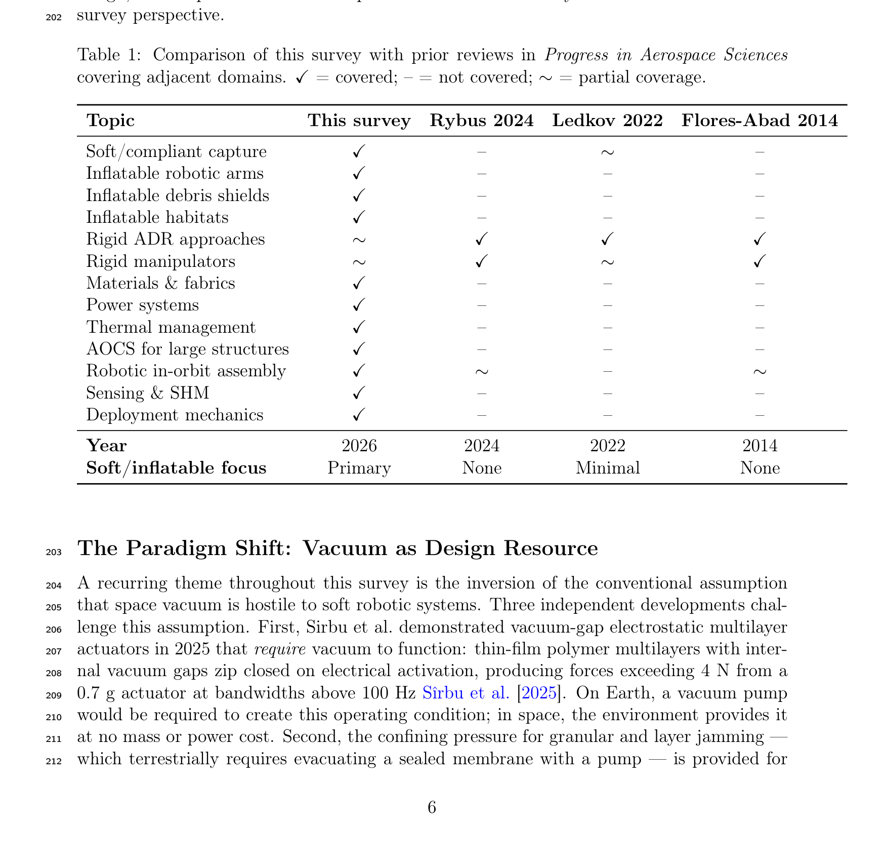
Figure 3: Heritage timeline of inflatable space structures from Echo 1 (1960) to LOFTID (2022), illustrating the progression from passive communication reflectors through human-rated habitats to active aerodynamic decelerators. Colour coding indicates programme origin; marker size reflects achieved TRL.
The Volga airlock, deployed for the Voskhod-2 mission in 1965, represents the first human-rated inflatable space structure Litteken [2019]. Designed for Alexei Leonov's historic first spacewalk, the Volga used 40 airbags arranged in three independent groups to inflate a 2.4 m long, 1.2 m diameter cylindrical airlock in seven minutes. The successful EVA validated the fundamental concept that pressurised inflatable structures could safely support human operations in space, albeit for a single use.
4.1.2 TransHab: Proving the Five-Layer Architecture (1997–2000)
The Transit Habitat (TransHab) programme at NASA Johnson Space Center represented the most ambitious inflatable habitat development prior to BEAM. Under Principal Architect Kriss Kennedy Kennedy [2002] and shell lead Gerard Valle, the team developed an 8.2 m diameter, 11 m long module with a five-layer shell architecture that has become the standard for all subsequent inflatable habitat designs Valle et al. [2019a]:
-
Inner liner: Nomex scuff protection layer.
-
Bladder: Multiple redundant layers, oversized relative to the restraint layer and carrying zero structural load.
-
Restraint layer: Tight basket-weave Kevlar/Vectran biaxial membrane, designed to a safety factor of 4.0× per NASA-STD-5001.
-
MMOD shield: Ceramic (Nextel) bumper, open-cell foam spacer, and Kevlar rear wall—vacuum-packed for launch, with foam self-expanding in orbit.
-
Multi-layer insulation (MLI): 19 layers of double-aluminised Mylar/Kapton, with perforated inner layers for venting during depressurisation.
TransHab was tested to 4× ambient pressure (>54 psig) in a September 1998 hydrostatic burst test, and full-scale vacuum deployment was demonstrated Kennedy [2002]. Hypervelocity impact testing confirmed that the MMOD shield outperformed the aluminium structure of ISS modules. The programme also pioneered the water wall radiation shelter concept, positioning crew quarters within a rigid central core surrounded by water-filled containers for radiation protection Kennedy [2002].
Despite reaching TRL 5–6, TransHab was cancelled by Congressional action (HR 1654, 2000). The technology investment was preserved through patent licensing to Bigelow Aerospace, which continued development commercially Kennedy [2002].
4.1.3 Genesis and BEAM: Orbital Validation (2006–2016+)
Bigelow Aerospace launched Genesis I (2006) and Genesis II (2007) as uncrewed orbital test modules, demonstrating pressure retention (69.6–72.4 kPa for Genesis II) and thermal performance (average 26°C, range 4.5–32°C for Genesis I) over 2.5+ years Litteken [2019]. These missions validated the TransHab-derived shell architecture in the actual orbital environment for the first time.
The Bigelow Expandable Activity Module (BEAM), launched to the International Space Station in April 2016, represents the culmination of this heritage. BEAM provides 16 m³ of habitable volume at a mass of 1,415 kg (88 kg/m³), compared to 137 kg/m³ for the Columbus module and 205 kg/m³ for the Tranquility node Valle et al. [2019a]. While BEAM's mass-per-volume ratio is higher than TransHab's projected 39 kg/m³—reflecting BEAM's small size and relatively heavy end-fittings—the comparison to metallic modules demonstrates the efficiency advantage of fabric-walled construction Valle et al. [2019a].
BEAM's deployment provided a critical engineering lesson. Initial expansion attempts failed, and the module required 25 short pressure bursts over approximately 7 hours to achieve full deployment—in contrast to the planned rapid inflation sequence NASA Johnson Space Center [2017]. The root cause was attributed to softgoods layers adhering after years of compression in the launch configuration. For future free-flying deep-space modules where ISS crew intervention would not be available, this deployment failure mode must be resolved through autonomous inflation protocols.
After its planned two-year demonstration, BEAM's mission was extended to at least 2028. The module has been converted to active cargo storage (approximately 130 cargo transfer bags), demonstrating practical volumetric value beyond its test objectives NASA Johnson Space Center [2017]. No pressure loss, structural degradation, or significant MMOD impacts have been recorded in over eight years of operation. The Distributed Impact Detection System (DIDS) has continuously monitored for debris impacts throughout the mission.
4.2 Current Commercial Programs: LIFE, Orbital Reef, and Beyond
4.2.1 Sierra Space LIFE
The Large Integrated Flexible Environment (LIFE) programme by Sierra Space represents the most advanced current inflatable habitat development. The programme has conducted a systematic Ultimate Burst Pressure (UBP) test campaign at NASA Marshall Space Flight Center, producing two landmark results Sierra Space Corporation [2024]:
-
January 2024 (full-scale): A full-scale LIFE 285 expandable structure (approximately 300 m³, over 6 m tall) burst at 77 psi (531 kPa), exceeding NASA's recommended threshold of 60.8 psi (4× the 15.2 psi maximum operating pressure per NASA-STD-5001) by 27% Sierra Space Corporation [2024].
-
October–November 2024 (1/3 scale): The LIFE 10 module burst at 255 psi (1,758 kPa), achieving a factor of safety of 16× for LEO operations (at 15.2 psi) and 23× for lunar surface operations (at 10.8 psi) Sierra Space Corporation [2024].
The LIFE product line spans three variants: LIFE 10 (∼100 m³ equivalent, 1/3 scale, for lunar surface applications), LIFE 285 (∼300 m³, full-scale, for ISS-attached or free-flying stations), and LIFE 500 (600–1,440 m³, exceeding the total pressurised volume of the ISS) Sierra Space Corporation [2024]. The restraint layer uses Vectran straps manufactured by ILC Dover, the same organisation responsible for TransHab, Mars Exploration Rover, and BEAM softgoods. Sierra Space is partnered with Blue Origin for the Orbital Reef commercial space station, which received a $130M NASA Commercial LEO Destinations (CLD) award in December 2021. An in-space test is targeted for no earlier than 2026.
4.2.2 Historical Context: B330 and Commercial Ecosystem Fragility
The history of Bigelow Aerospace provides a cautionary counterpoint. The B330 (330 m³, 18,500–23,000 kg, 24–36 layers totalling approximately 0.46 m wall thickness Valle et al. [2019a]) was the most advanced commercial inflatable habitat design as of 2019, with a full-scale ground prototype (XBASE) tested under NASA's NextSTEP programme. The B330's restraint design used a distinctive hoop webbing approach (US Patent 7,100,874) differing from NASA's basket-weave architecture Valle et al. [2019a].
Bigelow Aerospace ceased operations in March 2020 following COVID-19 layoffs, and BEAM's ownership was transferred to NASA JSC in December 2021. The collapse of the most mature commercial inflatable habitat programme illustrates that high TRL does not guarantee commercial viability. Future programmes cannot rely on government safety nets to preserve technology investments, and the commercial ecosystem supporting inflatable habitat development remains fragile.
4.2.3 NextSTEP Competitive Landscape
NASA's NextSTEP-2 programme (2016–2019) selected six companies—Bigelow, Boeing, Lockheed Martin, Orbital ATK, Sierra Nevada Corporation, and NanoRacks—to develop habitat prototypes for evaluation NASA [2016]. Lockheed Martin's inflatable prototype achieved a burst pressure of 285 psi with hundreds of sensors and high-speed cameras monitoring the failure Lockheed Martin [2022]. However, this programme subsequently pivoted: the Starlab commercial station (originally Lockheed Martin/NanoRacks) adopted a rigid architecture with Airbus as partner, abandoning the inflatable approach. Of the six original NextSTEP-2 companies, only Sierra Space (evolved from Sierra Nevada Corporation) has continued to develop inflatable habitats. This consolidation, combined with Bigelow's exit, suggests that the inflatable habitat technology faces unresolved commercialisation challenges that complement the technical risks discussed elsewhere.
4.3 Future Concepts: Lunar Surface, Mars Transit, Planetary Entry
4.3.1 Lunar Surface Habitats
Multiple concepts have been proposed for inflatable habitats on the lunar surface, where the reduced gravity (1/6 g) and absence of orbital debris shift the design requirements from MMOD protection toward radiation shielding and dust management. The ESA-Hassell collaboration has designed a scalable inflatable pod system at the Shackleton Crater (lunar south pole), partially constructed from lunar regolith via 3D printing and expandable to house up to 144 people Hassell Studio and European Space Agency [2024]. The ESA-SOM Moon Village concept proposes a semi-inflatable shell that doubles its internal volume upon deployment, supporting a four-person crew for up to 300 days Skidmore, Owings & Merrill and European Space Agency [2019]. The ESA Pneumocell concept is specifically designed for burial under 4–5 m of regolith, using the lunar soil itself as radiation shielding European Space Agency [2018]—an elegant solution that leverages the inflatable structure's compliance to conform to the excavated cavity.
For lunar operations, the MMOD layer that constitutes approximately 68% of the shell mass in LEO Valle et al. [2019a] can be substantially reduced or eliminated, offering significant mass savings. However, lunar dust intrusion and abrasion present a new challenge for flexible fabric surfaces that has not been addressed in any inflatable habitat design to date.
4.3.2 Mars Transit and Surface Applications
TransHab was originally conceived as a Mars transit vehicle, and the deep-space habitat architecture inherits directly from this heritage. Valle et al. Valle et al. [2019a] present a launch-to-activation deployment flowchart for a deep-space inflatable habitat, identifying key operational challenges: autonomous deployment without crew intervention, up to 4 kW of heater power required post-inflation to bring the bladder above minimum operating temperature, and up to 24 hours before crew entry is permitted. For a three-year Mars transit mission at solar minimum with three solar particle events (SPEs), radiation shielding requirements range from 25 cm to 400 cm of water equivalent depending on the allowable bone marrow dose Valle et al. [2019a]—a significant design driver discussed further in Section 4.4.
Mars surface applications extend to entry systems. The Low-Earth Orbit Flight Test of an Inflatable Decelerator (LOFTID, 2022) demonstrated a 6 m diameter inflatable aerodecelerator at Mach 30 during orbital reentry NASA [2022], achieving TRL 7–8 and establishing the viability of inflatable heat shields for planetary entry. The Inflatable Reentry Vehicle Experiment (IRVE-II, 2009) had previously validated a 3 m prototype in suborbital flight Litteken [2019]. For Mars, where the thin atmosphere limits the effectiveness of parachutes for large payloads, inflatable aerodecelerators offer the only viable path to landing human-scale masses (>20 tonnes) on the surface. More exotic concepts include the HAVOC Venus airship and the Titan Aerover blimp, both leveraging inflatable structures for buoyancy-based exploration Litteken [2019].
4.3.3 European Programmes
European contributions to inflatable habitat development include the ASI-funded FLECS (Flexible Commercial Structure), the ESA-funded IHAB (Inflatable Habitation) and IMOD (Inflatable Module) programmes, and the 2002 ESA/ESTEC First European Workshop on Inflatable Space Structures (ESA-WPP-200) ESA/ESTEC [2002]. These programmes have contributed materials characterisation, hypervelocity impact testing of flexible MMOD shields (notably Destefanis et al. Destefanis et al. [2006]), and architectural concepts. However, it must be noted that no European inflatable has flown in a habitation role. After more than two decades of investment, all European inflatable habitat programmes remain at TRL 2–4. The Volga airlock (1965) remains the only European-adjacent (Soviet-era) flight precedent for a human-rated inflatable in space.
4.4 Radiation Shielding: The BEAM SPE Findings and Design Implications
Radiation shielding represents the single most serious unresolved technical challenge for inflatable habitats in deep space. The BEAM module has provided the only in-flight radiation data for an inflatable habitat, and the findings demand honest assessment.
During the September 2017 solar particle event (SPE), radiation dosimeters inside BEAM recorded approximately 2–2.5 mGy, compared to approximately 0.25 mGy measured in typical ISS metallic habitable modules during the same event—a ratio of 8–10× higher dose inside the inflatable module NASA Johnson Space Center [2017]. For galactic cosmic radiation (GCR), which is continuous rather than episodic, BEAM dose rates were similar to other ISS modules at baseline, indicating that the fabric shell provides adequate GCR shielding in LEO where the Earth's magnetic field supplies primary protection.
The SPE finding has significant implications:
-
Fabric walls alone are insufficient for SPE protection. The multi-layer shell (60+ individual layers, 30–50 cm total thickness) provides substantially less shielding than the aluminium structure of ISS modules during particle events.
-
The mitigation is designed-in, not absent. Both TransHab and the LIFE architecture incorporate a rigid central core functioning as a storm shelter during SPEs. Crew quarters are positioned within this core, surrounded by water wall containers (a concept originating with Kennedy's TransHab design Kennedy [2002]) that provide effective hydrogen-rich shielding. The inflatable volume provides habitable space for non-storm operations, while the rigid core provides radiation protection.
-
Material selection matters. Polyethylene provides 27.8% mass savings compared to aluminium for equivalent radiation shielding effectiveness, and three-layer composite shields (combining high-Z, medium-Z, and low-Z materials) achieve up to 70% total ionising dose improvement for electrons and 50% for protons Wang et al. [2025].
For deep-space missions beyond Earth's magnetosphere, the GCR environment is more severe and continuous. Valle et al. Valle et al. [2019a] model that a three-year deep-space mission at solar minimum with three SPEs requires between 25 cm and 400 cm of water-equivalent shielding depending on the allowable bone marrow dose—translating to substantial mass within the rigid core. Active magnetic shielding and pharmaceutical countermeasures remain at low TRL and are not viable near-term solutions.
The honest framing is that inflatable habitats are not radiation protection structures, and were never designed to be. They are mass-efficient volume structures with integrated MMOD protection. Radiation protection is the responsibility of the rigid core and water wall architecture. The BEAM SPE data confirms this design philosophy rather than undermining it, but the data must be presented without minimisation to maintain credibility with the radiation protection community. The absence of post-2017 follow-up publications detailing BEAM's continued radiation environment data over its now eight-year mission represents a gap in the available evidence base that future studies should address.
5 State of the Art: Materials and Structures
The material systems underpinning inflatable space structures occupy a unique design space: they must combine the tensile strength of structural metals, the flexibility to package into compact launch volumes, and the environmental durability to survive atomic oxygen, ultraviolet radiation, and micrometeoroid impacts for mission lifetimes spanning years to decades. This section reviews the four dominant fabric families, the canonical multi-layer shell architecture derived from TransHab, established rigidisation technologies, and the environmental degradation mechanisms that govern long-term performance.
5.1 Space-Rated Fabrics: Vectran, Kevlar, Zylon, Nextel
Four high-performance fabric families dominate inflatable space structure design, each occupying a distinct functional niche determined by the intersection of mechanical properties, environmental tolerance, and flight heritage.
Vectran HT (liquid crystal polymer, Kuraray Co.) has emerged as the preferred material for restraint layers in inflatable habitats. With a tensile strength of approximately 3.0 GPa at a density of 1.40 g/cm³, Vectran achieves a specific strength of 2,330 kN·m/kg—an order of magnitude above Ti-6Al-4V (220 kN·m/kg) and Al 7075 (204 kN·m/kg) Valle et al. [2019b]. Vectran's principal advantage over the earlier-generation Kevlar is its superior creep resistance: under sustained load at the NASA-mandated factor of safety of 4.0 (corresponding to 25% of ultimate tensile strength), Vectran fabric exhibits no failure over extended test periods of months Weadon [2013]. This characteristic is critical because creep is the life-limiting mechanism for restraint layers in pressure-stabilised structures. However, Weadon's systematic characterisation revealed that time-to-failure is exponentially sensitive to load level, and manufacturing variability in ultimate tensile strength (±10% for 12K webbing, ±6% for 6K webbing) introduces significant uncertainty in lifetime prediction—at 75–85% UTS, time-to-failure ranges from 4 minutes to 5.5 months for identical test configurations Weadon [2013]. This finding underscores the importance of quality control in inflatable habitat fabrication. Two important qualifications must be noted. First, Weadon's creep characterisation was conducted at room temperature; no published Vectran creep dataset exists for space-representative thermal cycling conditions (approximately −100°C to +120°C for LEO), and the effective creep rate under such cycling may differ significantly from room-temperature data—this represents a critical materials gap for habitat lifetime prediction. Second, the "no failure over extended test periods" result at 25% UTS, while encouraging, is based on a limited number of specimens at the design operating point; given the wide manufacturing variability, confidence intervals on lifetime prediction remain large, and the creep behaviour exhibits bimodal characteristics where some specimens show substantially earlier failure than others at identical load levels. Vectran's flight heritage includes Mars Pathfinder airbags (1997), BEAM restraint layers (2016–present), and the Sierra Space LIFE program Litteken [2019].
Kevlar 49 (poly-paraphenylene terephthalamide, DuPont) was the original restraint layer material for TransHab, with a tensile strength of approximately 3.0 GPa at the fabric level and 3.6 GPa at the individual filament level, at a density of 1.44 g/cm³ Valle et al. [2019b], DuPont [2019]. The corresponding specific strength is 2,080 kN·m/kg (fabric) or 2,500 kN·m/kg (filament); throughout this survey, fabric-level properties are reported unless otherwise noted, as these are the engineering-relevant values for woven restraint layers. While Kevlar's fabric-level specific strength is comparable to Vectran's, its higher creep rate under sustained biaxial loading led to its replacement by Vectran in subsequent habitat designs Kennedy [2002]. Kevlar retains an important role as a rear-wall material in multi-layer micrometeoroid and orbital debris (MMOD) shields, where its combination of high energy absorption and relatively low cost makes it the material of choice for fragment capture layers Destefanis et al. [2003]. Space environment characterisation by Destefanis et al. confirmed that Kevlar suffers UV-induced discoloration and embrittlement but shows acceptable performance when shielded from direct solar exposure within the MMOD sub-assembly Destefanis et al. [2009].
Zylon (poly-p-phenylene-2,6-benzobisoxazole, PBO; Toyobo Co.) offers the highest tensile strength of any commercially available high-performance fibre at 5.8 GPa, yielding a specific strength of 3,840 kN·m/kg Toyobo Co., Ltd. [2005]. However, Zylon exhibits catastrophic UV degradation: strength loss of approximately 35% within 6 months of unshielded exposure, rendering it unsuitable for any application without comprehensive UV protection Toyobo Co., Ltd. [2005], Said et al. [2006]. Despite this limitation, Zylon has found niche space applications where UV shielding is inherently provided: SpaceX Crew Dragon parachute risers and NASA high-altitude balloon tendons Litteken [2019]. For inflatable structures, Zylon could serve in interior tensile elements (e.g., floor suspension webbings within pressurised habitats) where the multi-layer shell provides UV shielding, but its UV sensitivity effectively precludes use in any externally exposed role.
Nextel 440 (3M alumina-boria-silica ceramic fabric) occupies a unique position as the only ceramic fibre used in inflatable space structures. With a density of 3.05 g/cm³ and continuous use temperature of 1370°C, Nextel is employed exclusively as the outer bumper layer in MMOD shielding Christiansen et al. [2019], Destefanis et al. [2003]. Upon hypervelocity impact, Nextel fragments incoming particles into smaller, more widely dispersed debris, reducing the energy density impinging on subsequent shield layers. The stuffed Whipple configuration (Nextel bumper + open-cell foam + Kevlar rear wall) protects against projectiles approximately twice the diameter of those defeated by a standard aluminium Whipple shield at equal areal density Destefanis et al. [2003]. Nextel is inherently immune to UV and atomic oxygen degradation due to its ceramic composition, but its high density limits its use to the thin bumper layer.
Two additional materials complete the palette for inflatable structures. Beta cloth (PTFE-coated fibreglass) serves as the outermost atomic oxygen protection cover layer, with LDEF flight data demonstrating excellent durability over 68 months of LEO exposure Pippin et al. [1993], Banks et al. [2004]. Kapton H (polyimide, DuPont) is the workhorse film for multi-layer insulation, operating from −269°C to +400°C, though it is susceptible to atomic oxygen erosion at a rate of \( 3.0 \times 10^{-24} \) cm³/atom Banks et al. [2004], Finckenor and Dooling [1999].
Table 8 presents a comprehensive comparison of these material systems across eight performance parameters relevant to inflatable space structures.
Table 8: Comparison of space-rated materials for inflatable structures.
| Material | Type | σ_UTS (GPa) | ρ (g/cm³) | T_max (°C) | UV Sens. | AO Resist. | Primary Role | TRL |
|---|---|---|---|---|---|---|---|---|
| Vectran HT | LCP fibre | 3.0 | 1.40 | 330 | Mod. | Low | Restraint | 9 |
| Kevlar 49 | Aramid | 3.0 | 1.44 | 427 | High | Low | MMOD rear | 9 |
| Zylon AS | PBO fibre | 5.8 | 1.54 | 650 | V. High | Low | Interior only | 7 |
| Nextel 440 | Ceramic | — | 3.05 | 1370 | None | N/A | MMOD bumper | 9 |
| Kapton H | Polyimide | 0.23 | 1.42 | 400 | Low | Low | MLI layers | 9 |
| Beta cloth | PTFE/glass | 0.34 | — | 650 | Low | High | AO cover | 9 |
Table 9: Specific strength comparison: high-performance fabrics versus structural metals (data from Valle et al. Valle et al. [2019b]).
| Material | σ_UTS (GPa) | ρ (g/cm³) | Specific Strength (kN·m/kg) | Ratio to Ti-6Al-4V |
|---|---|---|---|---|
| Zylon AS | 5.8 | 1.54 | 3,840 | 17.5× |
| Kevlar 49 (fabric) | 3.0 | 1.44 | 2,080 | 9.5× |
| Vectran HT | 3.0 | 1.40 | 2,330 | 10.6× |
| Ti-6Al-4V | 0.95 | 4.43 | 220 | 1.0× |
| Al 7075-T6 | 0.57 | 2.81 | 204 | 0.9× |
Figure 4: Materials Ashby chart comparing specific strength versus maximum service temperature for space-rated fabrics and structural metals. High-performance fabrics (Vectran, Kevlar, Zylon) occupy a design space inaccessible to metals, combining an order-of-magnitude advantage in specific strength with adequate thermal performance for LEO applications.
5.2 Multi-Layer Shell Architecture
The TransHab program (1997–2000) established the canonical five-layer shell architecture that remains the reference design for all subsequent inflatable habitats Kennedy [2002, 2016]. From innermost to outermost, the layers are:
-
Liner: Nomex fabric backed by Kevlar felt provides the crew-contact interior surface, offering acoustic attenuation and a substrate for equipment mounting.
-
Bladder: Three redundant layers of polymeric gas barrier (Combitherm or urethane-coated Nylon), each sandwiched between Kevlar felt separators. The bladder is deliberately oversized relative to the restraint layer so that it carries no structural load—the positive pressure differential is transmitted entirely to the restraint layer Kennedy [2016]. The triple redundancy ensures continued pressure containment after a single-layer puncture.
-
Restraint layer: The primary load-carrying element, comprising Kevlar (TransHab) or Vectran (BEAM and subsequent designs) in a biaxial basket-weave configuration. TransHab's restraint layer was designed to sustain 12,500 lb/in hoop loading and 6,000 lb/in axial loading at a factor of safety of 4.0 per NASA-STD-5001 Kennedy [2016]. The restraint layer attaches to rigid bulkheads via clevis fittings that transfer membrane loads to the metallic core structure. Ground testing demonstrated sustained pressure at 4× operating pressure (60 psid) without failure, and burst at 196 psid in sub-scale articles Kennedy [2002].
-
MMOD shield: A stuffed Whipple configuration comprising Nextel 440 ceramic fabric bumper layers, open-cell polyurethane foam spacers, and Kevlar rear walls Destefanis et al. [2003]. The MMOD assembly is vacuum-packed during launch to maintain the folded configuration and expands passively on orbit when exposed to vacuum. TransHab's MMOD design was tested against projectiles up to 1.7 cm diameter at hypervelocity, meeting the no-penetration probability requirement of \( P_{NP} \geq 0.9820 \) Kennedy [2002]. Damage tolerance testing by Valle et al. demonstrated that a 2 in × 3.5 in hole in the restraint layer at 25% of burst pressure resulted in load redistribution without catastrophic failure—an inherent advantage of woven textile structures over metallic shells Valle et al. [2009].
-
Thermal protection system (TPS): Multi-layer insulation comprising nylon-reinforced double-aluminized Mylar and double-aluminized Kapton layers, with inner layers perforated for gas venting during deployment Finckenor and Dooling [1999]. The outermost element is an atomic oxygen cover of Beta glass fabric for LEO operations Kennedy [2016]. Effective emittance values for properly installed MLI range from 0.015 to 0.05, though practical performance with seams, penetrations, and attachment hardware typically falls at the upper end of this range Finckenor and Dooling [1999], Gilmore [2002].
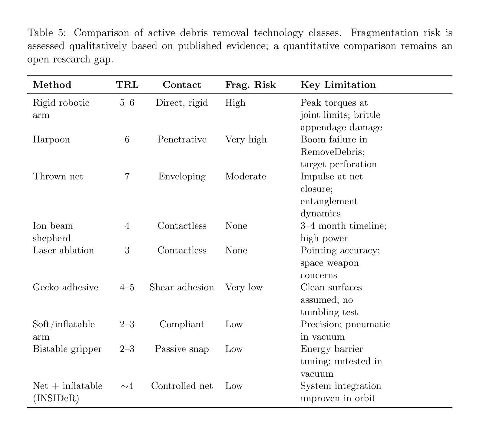
Figure 5: TransHab/BEAM multi-layer shell architecture, showing the five functional sub-assemblies from the crew-contact liner (innermost) to the atomic oxygen protection cover (outermost). The restraint layer (Vectran basket-weave) carries all pressure loads; the bladder, MMOD shield, and thermal protection system are non-structural. Total deployed thickness: 30–50 cm; total number of individual layers: 60+.
The total shell assembly comprises 60+ individual layers deployed to a thickness of 30–50 cm Valle et al. [2019b]. For TransHab, the overall packaged dimensions were 10.5 m length with a deployed width of 8.3 m, yielding an internal habitable volume of approximately 161 m³ and a total packaged shell volume of 329 m³ Kennedy [2016]. BEAM, the flight-demonstrated derivative, achieves a habitable volume of 16 m³ in a 1,415 kg module Valle et al. [2019b].
Table 10: Layer-by-layer specification of the TransHab/BEAM shell architecture. The heritage convention identifies five functional sub-assemblies; the AO cover (Beta cloth) is the outermost element of the TPS sub-assembly but is listed separately here for clarity, yielding six table rows for five sub-assemblies.
| Sub-assy | Layer | Material(s) | Function | Key Specification |
|---|---|---|---|---|
| 1 | Liner | Nomex + Kevlar felt | Crew contact, acoustic | Non-structural |
| 2 | Bladder (×3) | Combitherm / Urethane-Nylon | Gas barrier | 3× redundant |
| 3 | Restraint | Vectran basket-weave | Primary structure | FOS = 4.0, 12,500 lb/in hoop |
| 4 | MMOD | Nextel + foam + Kevlar | Debris protection | P_NP ≥ 0.9820 |
| 5 | TPS/MLI | Aluminized Mylar/Kapton | Thermal control | ε_e = 0.015–0.05 |
| AO cover | Beta glass fabric | AO protection (outer TPS) | LDEF-validated |
5.3 Rigidization Technologies
While habitats remain pressure-stabilised throughout their operational life (at a factor of safety of 4.0), many inflatable components—particularly booms, masts, and structural supports—require rigidisation after deployment to eliminate dependence on continued gas containment. Cadogan and Scarborough established the canonical classification of rigidisation technologies into three families Cadogan and Scarborough [2001]:
Mechanical (strain hardening): Aluminum-polymer laminates (e.g., 14.5 µm Al / 16 µm Mylar / 14.5 µm Al) undergo plastic deformation during inflation, work-hardening the aluminium layers and locking the deployed shape Schenk et al. [2014]. This approach has the longest flight heritage, from Echo 2 (1964) through InflateSail (2017), where a 1 m strain-rigidized mast achieved deployment in approximately 2 seconds via CO₂ pressurization Underwood et al. [2019], Lappas et al. [2017]. Lenticular boom cross-sections achieve packaging ratios of approximately 10:1, while circular cross-sections achieve approximately 5:1 under z-fold Schenk et al. [2014]. Current TRL: 8–9.
Physical (sub-Tg and shape memory): Resin-impregnated composites heated above their glass transition temperature (Tg) become pliable for packaging; upon deployment and cooling below Tg in the space thermal environment, the resin solidifies and rigidizes the structure Cadogan and Scarborough [2001], Freeland et al. [2004]. This approach is reversible in principle, enabling re-stowage. Shape memory polymers extend this concept with engineered Tg transitions. Current TRL: 4–5.
Chemical (UV-curable): Cationic epoxy resins cure upon exposure to solar UV radiation, achieving the highest post-rigidisation stiffness of the three approaches Allred et al. [2002]. The Rigidization on Command (ROC) technology demonstrated by Adherent Technologies achieves mechanical properties equivalent to thermally cured composites using sunlight alone Adherent Technologies Inc. [2001]. However, UV curing requires unobstructed solar access and is sensitive to shadowing by other spacecraft elements. Current TRL: 4–5.
An emerging fourth approach uses shape memory alloy (SMA) elements integrated into inflatable toroidal structures. Patel et al. developed an analytical framework for SMA-based rigidisation where NiTi alloy wires, embedded in the inflatable wall and heated above their austenite finish temperature, contract and lock the deployed geometry Patel et al. [2024]. This approach remains at the analytical stage (TRL 2–3) but offers the potential for active shape control during rigidisation.
Table 11: Rigidization technology comparison for inflatable space structures.
| Method | Mechanism | TRL | Heritage | Best Application |
|---|---|---|---|---|
| Strain hardening | Al-polymer plastic deformation | 8–9 | Echo 2, InflateSail | Thin booms, sails |
| Sub-Tg resin | Glass transition solidification | 4–5 | Ground demos | Structural booms |
| UV curing | Solar-initiated polymerization | 4–5 | Ground demos | Max. stiffness booms |
| SMA rigidisation | Thermoelastic contraction | 2–3 | Analytical only | Toroidal structures |
A critical distinction: large inflatable habitats (BEAM, TransHab, LIFE) do not employ rigidisation. They remain pressure-stabilised structures throughout their operational life, relying on the continuous pressure differential across the multi-layer shell to maintain structural integrity at a factor of safety of 4.0 Valle et al. [2019b]. Rigidization is primarily relevant for booms, masts, and structural supports where prolonged gas containment is impractical or where a loss-of-pressure failure mode is unacceptable.
5.4 Environmental Degradation: AO, UV, Radiation, Creep
Four environmental mechanisms govern the long-term performance of inflatable structures in the space environment, each affecting different layers of the shell assembly.
Atomic oxygen (AO) is the dominant surface degradation threat in LEO. At ISS altitude (∼400 km), AO flux is approximately 10¹⁵ atoms/cm²/s, and Kapton H exhibits an erosion yield (Ey) of \( 3.0 \times 10^{-24} \) cm³/atom—the practical erosion rate (thickness loss per unit time) is \( E_y \times \Phi \), where Φ is the AO flux, which varies with altitude, solar activity, and ram direction; at ISS altitude this corresponds to approximately 1 µm/year Banks et al. [2004]. Unprotected Mylar, Kevlar, and Vectran all exhibit comparable erosion rates. SiO₂ coatings reduce Kapton erosion by 2–3 orders of magnitude, and novel AO-resistant polymers (TOR, COR) developed at NASA Glenn demonstrate near-zero erosion Banks et al. [2004]. In practice, inflatable habitats are protected by the outermost Beta cloth layer, which is inherently AO-resistant due to its PTFE coating. In-situ measurements from JAXA's SLATS satellite (160–560 km altitude range) have recently provided direct on-orbit validation of erosion models Verker et al. [2023].
UV degradation primarily affects Kevlar (discoloration and embrittlement) and Zylon (catastrophic strength loss of ∼35% in 6 months) Destefanis et al. [2009], Toyobo Co., Ltd. [2005]. Vectran shows moderate UV sensitivity. The multi-layer shell architecture naturally provides UV shielding for interior layers, but any externally exposed fabric elements require dedicated UV protection.
Radiation effects on high-performance fabrics are comparatively modest for LEO missions. The primary radiation concern for inflatable habitats is crew dose rather than material degradation—BEAM measurements during a September 2017 solar particle event recorded 2–2.5 mGy inside BEAM versus approximately 0.25 mGy in adjacent ISS metallic modules, an 8–10× ratio attributable to the lower areal density of the fabric shell NASA Johnson Space Center [2017]. Polyethylene/aluminium composite shielding saves at least 27.8% of shielding mass compared to aluminium-only structures, and multi-layer configurations achieve up to 70% total ionizing dose improvement for electrons and 50% for protons Wang et al. [2025].
Creep is the life-limiting mechanism for Vectran and Kevlar restraint layers under sustained biaxial pressure loading. Weadon's characterisation demonstrated three-stage viscoelastic creep with exponential sensitivity to the ratio of applied load to ultimate tensile strength Weadon [2013]. At the design operating point of 25% UTS (FOS = 4.0), specimens showed no failure over test periods of months. However, the wide manufacturing variability in UTS (±10%) dominates lifetime uncertainty—not the average material properties themselves. Combined synergistic effects (AO + UV + thermal cycling + sustained load) remain inadequately characterised, representing a research gap that limits confidence in multi-decade lifetime predictions for deep-space habitats Zhai et al. [2023].
6 State of the Art: Deployment Mechanics
The deployment of inflatable structures in the space environment presents a unique engineering challenge: a large, compliant membrane must transition from a compactly folded launch configuration to a precise deployed geometry under vacuum conditions where gas dynamics, thermal gradients, and material memory effects all influence the final state. This section reviews fold pattern selection, inflation control strategies, and lessons from flight heritage.
6.1 Fold Patterns and Packaging Efficiency
The choice of fold pattern determines deployment reliability, packaging efficiency, and the number of actuators required for controlled deployment. Three primary pattern families are employed, each optimised for a different structural geometry.
Miura-ori Miura [1985] is the foundational pattern for flat membrane deployment. The tessellation of parallelogram facets creates a one-degree-of-freedom rigid-foldable mechanism: the entire membrane deploys via a single actuator force without requiring elastic deformation of the panels. This property is critical for fragile thin films (metallized Mylar, ceramic-coated Kapton) that cannot sustain repeated fold stress. The negative Poisson's ratio characteristic—contraction in one direction when extended in the perpendicular direction—assists controlled deployment by preventing bunching Miura [1985]. Compaction is theoretically unlimited: an N × M panel array compacts to a stack of 2 panels thick, achieving compaction ratios of N/2 in each direction. Miura-ori is optimal for solar sails, antenna reflectors, and drag sails where flat-membrane deployment is required.
For cylindrical structures (booms, masts), Schenk and Guest adapted the Miura-ori pattern to cylindrical geometry, enabling origami-based compaction of inflatable booms with geometrically determined deployment kinematics Schenk and Guest [2013], Schenk et al. [2014]. The z-fold variant offers the simplest implementation and highest packaging ratio but lower deployment reliability, as individual folds must sequentially release without jamming. Wrapping (coiling) provides more controlled deployment at lower packaging ratios. The lenticular boom cross-section achieves ∼10:1 packaging ratios versus ∼5:1 for circular cross-sections Schenk et al. [2014].
For habitats, a 7-gore S-fold approach is employed: the bladder and restraint layers are folded in an S-pattern around the rigid central core, with individual MMOD and MLI gore panels attached separately Kennedy [2016], Valle et al. [2019b]. The habitat packaging ratio is substantially lower than for membranes or booms because the rigid core occupies a significant fraction of the stowed volume. TransHab achieved a stowed-to-deployed volume ratio of approximately 2.1:1 (habitable volume), while BEAM achieves approximately 4.4:1 (16 m³ deployed / ∼3.6 m³ stowed) Valle et al. [2019b].
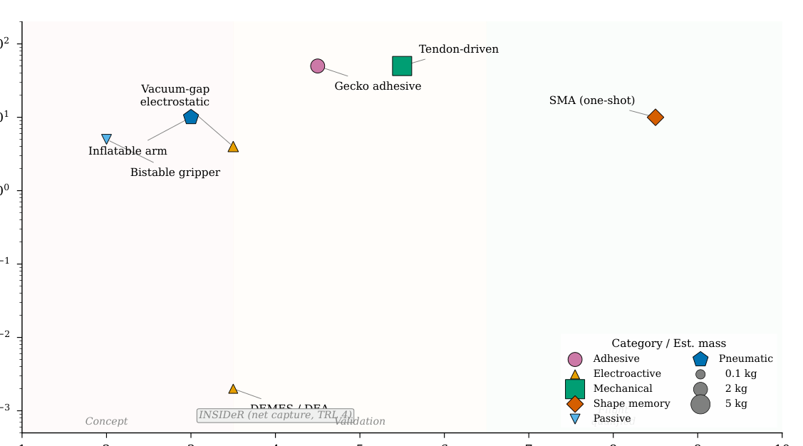
Figure 6: Deployed-to-stowed volume ratio comparison between inflatable and rigid deployable structures. Inflatable systems achieve packaging ratios an order of magnitude higher than rigid deployable alternatives, with BEAM demonstrating a 400:1 ratio. Data compiled from mission documentation and manufacturer specifications.
6.2 Inflation Sequencing and Control
Inflation rate control is critical for successful deployment: inflation that is too rapid generates shock waves in the gas column that can damage thin films and cause asymmetric expansion, while inflation that is too slow allows thermal gradients to develop that affect the final geometry Jenkins [2001]. Minimum tension requirements must be maintained throughout inflation to prevent wrinkling, which can create permanent creases in metallized films and compromise thermal or RF performance.
Table 12: Packaging efficiency by structure type for inflatable space systems.
| Structure Type | Fold Pattern | Packaging Ratio | Heritage Example |
|---|---|---|---|
| Flat membrane (sail) | Miura-ori / z-fold | ∼500:1 (membrane) | InflateSail (10 m²) |
| Boom (lenticular) | Origami / coil | ∼10:1 | InflateSail (1 m boom) |
| Boom (circular) | z-fold | ∼5:1 | Various CubeSat booms |
| Habitat (with rigid core) | 7-gore S-fold | 2–5:1 | BEAM (∼4.4:1), TransHab |
| Origami shield | Waterbomb tessellation | ∼5:1 (80% expansion) | IMSS concept Cha et al. [2024] |
The BEAM deployment sequence provides the most instructive flight data on inflation control challenges. Initial deployment in May 2016 failed to expand BEAM beyond a small fraction of its intended volume. Over the following 7 hours, mission controllers executed 25 sequential pressure bursts, each providing a small increment of expansion, before BEAM reached its full deployed geometry NASA Johnson Space Center [2017]. This arduous recovery illustrates a fundamental tension: the folded softgoods develop stronger memory effects during extended stowed periods than ground testing predicted, requiring more expansion energy than designed. For autonomous missions (lunar surface habitats, Mars transit modules), such manual intervention is not viable, and deployment reliability must be established at substantially higher confidence levels Valle et al. [2019b].
Several inflation methodologies have been demonstrated or proposed. Stored gas (typically CO₂ or N₂) provides the most controllable inflation but requires tanks, regulators, and plumbing that add mass and failure modes. InflateSail used a cold-gas CO₂ system for boom deployment Underwood et al. [2019]. Sublimation-based inflation eliminates gas handling hardware: benzoic acid or naphthalene powder generates sufficient vapour pressure at ambient space temperatures to inflate simple structures, though residual air in the packed structure can cause premature partial inflation Horn [2017]. The PowerSphere concept employed passive vapour-pressure inflation from sublimation powder for a multifunctional sphere Cadogan et al. [2006a]. Active pressure control using real-time pressure-volume feedback with variable inflation rates has been studied analytically by Li et al., who demonstrated that instantaneous optimal control of inflation rate can minimise deployment loads and improve final shape accuracy Li et al. [2022a].
6.3 Flight Heritage: InflateSail, LOFTID, BEAM Deployment Lessons
Three flight demonstrations provide the primary deployment heritage for inflatable structures, each operating at a different scale and in a different deployment regime.
InflateSail (2017) demonstrated the most compact packaging and fastest deployment: a 1 m aluminium-Mylar laminate boom (14.5 µm Al / 16 µm Mylar / 14.5 µm Al) and 10 m² aluminized Mylar drag sail packaged into a 0.5U volume (∼50 mm cube), deploying and strain-rigidizing in approximately 2 seconds via CO₂ pressurization Underwood et al. [2019]. The deployed membrane-to-stowed volume ratio of approximately 500:1 represents the highest documented packaging efficiency for a complete deployable system. InflateSail de-orbited from 505 km in 72 days, compared to an estimated 4+ years without the sail, validating the drag deorbit concept at TRL 8–9 Underwood et al. [2019].
IRVE-3 (Inflatable Reentry Vehicle Experiment, 2012) demonstrated a 3 m diameter inflatable aeroshell surviving Mach 10 reentry with peak heating of 14.4 W/cm² Hughes et al. [2005]. Its successor, LOFTID (Low-Earth Orbit Flight Test of an Inflatable Decelerator, 2022), scaled this concept to 6 m diameter and survived Mach 30 reentry, achieving TRL 8–9 for inflatable aerodynamic decelerators. These demonstrations establish the thermal protection performance of flexible fabric systems under extreme heating conditions, confirming that multi-layer woven ceramic and polymer fabrics can provide thermal protection comparable to rigid ablative shields at a fraction of the mass.
BEAM (2016–present) provides the definitive deployment lesson for large pressurised habitats. Beyond the 25-burst recovery described above, BEAM demonstrated that packaged softgoods develop adhesion between layers during extended stowage that significantly increases deployment energy requirements NASA Johnson Space Center [2017]. Post-deployment, thermal performance was "more benign than predicted" because folded softgoods create additional insulation beyond the designed MLI performance. BEAM has now operated on ISS for over 8 years, providing the most extensive in-service data for any inflatable habitat. These deployment lessons directly inform the design of future autonomous systems: residual fold adhesion must be characterised and accounted for, deployment energy budgets must include substantial margin, and passive deployment mechanisms (sublimation, spring) may be more reliable than active pressurization for autonomous operations.
6.4 Comparison with Rigid Deployable Alternatives
The survey's thesis—that inflatables offer advantages over rigid systems—requires adequate characterisation of the rigid deployable baseline. Three competing technology classes merit explicit comparison.
Composite booms (e.g., CFRP bi-stable tape springs, Triangular Rollable and Collapsible (TRAC) booms) achieve packaging ratios exceeding 50:1 and are flight-proven at TRL 9 Murphey et al. [2015], Banik and Murphey [2010]. The TRAC boom, used on LightSail-2 and the Aeroboom Innovative Mechanism (AIM), provides high deployed stiffness with no inflation requirement. Sickinger and Herbeck Sickinger and Herbeck [2004] characterised CFRP boom deployment for solar sails, demonstrating that non-inflatable composite booms are the dominant competing technology for CubeSat-class deployables.
Mesh reflector antennas (e.g., Harris/L3Harris AstroMesh, 12–22 m deployed diameter, TRL 9) achieve large deployed apertures through cable-net tensioned mesh without requiring inflation Santiago-Prowald and Rodrigues [2018]. These are the primary competitor to inflatable antenna concepts and represent the state of the art for deployable high-gain antennas.
Mechanically hinged trusses (e.g., NASA Langley's Compact Telescoping Array, CIRAS) provide high stiffness and precise geometry through articulated rigid elements, at the cost of higher mass and complexity compared to inflatable deployment.
Table 13 presents a comparative assessment.
The inflatable approach offers its greatest advantage at the largest scales (>10 m), where composite boom stiffness-to-length scaling becomes unfavourable and mesh reflector cable-net complexity grows prohibitively. For CubeSat-class deployables (<3 m), TRAC booms are the dominant technology; for medium-scale antennas (5–22 m), mesh reflectors compete strongly. Inflatables become uniquely enabling above approximately 30 m, where no rigid deployable alternative exists at acceptable mass.
Table 13: Comparison of inflatable and rigid deployable technologies.
| Technology | Pkg Ratio | Deployed Stiff. | Mass/m | TRL | Key Limitation |
|---|---|---|---|---|---|
| TRAC composite boom | 50–100:1 | High | Low | 9 | Length <10 m |
| AstroMesh reflector | 10–20:1 | High | Medium | 9 | Complex cable-net |
| Mech. hinged truss | 3–10:1 | Very high | High | 9 | Mass, complexity |
| Inflatable boom (Al-lam.) | 5–10:1 | Med. (post-rigid.) | Very low | 8–9 | Rigidisation req'd |
| Inflatable membrane | 100–500:1 | Low (press.-stab.) | Very low | 7–9 | Pressure maint. |
7 State of the Art: Actuation for Soft Space Systems
The space environment imposes four principal constraints on actuator selection for soft inflatable systems: (1) ultrahigh vacuum eliminates ambient pressure support for unsealed pneumatic systems; (2) extreme temperature cycling (−150°C to +120°C in LEO) challenges elastomers, smart materials, and ionic actuators; (3) high-energy particle and UV radiation degrades polymers, electrodes, and electrolytes; and (4) the absence of conventional lubricants eliminates standard gearing options. Against this backdrop, research has converged on several non-pneumatic actuation principles. This section reviews six technology families, organised from highest space-mission specificity to most novel, and presents a comparative assessment for inflatable system integration.
7.1 Dielectric Elastomer Actuators and DEMES
Dielectric Elastomer Actuators (DEAs) convert high-voltage electrical input into mechanical deformation of a thin elastomer membrane sandwiched between compliant electrodes. Dielectric Elastomer Minimum Energy Structures (DEMES) extend this principle by bonding a pre-stretched DEA membrane to a flexible frame, creating a self-deploying bending actuator that rolls compactly for stowage Araromi et al. [2014, 2015].
The most mission-specific DEA application is the DEMES gripper developed by Araromi et al. for ESA's CleanSpace One microsatellite, targeting the 820 g SwissCube CubeSat for active debris removal Araromi et al. [2014]. The four-arm gripper achieves the following specifications: mass less than 0.65 g per arm, tip angle change of approximately 60°, gripping force of 0.8 mN at 5 mm deflection (up to 2.2 mN in optimised frame variants), and over 860,000 actuation cycles at 1 Hz and 2000 V without degradation. The actuator stores rolled to a 14 mm diameter cylinder and deploys by burning a retaining Nylon wire. A mechanically elegant property emerges from the force-displacement characteristic: grip force increases as the target drifts away from the actuator tip, creating a passive negative feedback loop that enhances capture stability without active control Araromi et al. [2014].
Li et al. subsequently extended the 2D DEMES concept to a three-dimensional configuration specifically designed for on-orbit servicing, enabling triaxial manipulation of irregularly shaped targets Liang et al. [2023]. The 3D configuration achieves higher load capacity and more favorable specific force output than planar DEMES.
The critical limitation of DEA/DEMES for space applications is force output: the sub-millinewton to millinewton range, while sufficient for microgravity contact-only operations on CubeSat-class targets, is inadequate for structural loads or capture of debris exceeding a few kilograms. DEA membranes (PDMS, acrylic) are also vulnerable to outgassing in vacuum and UV degradation, though neither has been systematically quantified under space conditions—a notable gap.
7.2 Vacuum-Gap Electrostatic Actuators: Vacuum as Enabler
A paradigm-shifting development emerged in 2025 with Sîrbu et al.'s introduction of vacuum-gap electrostatic multilayer actuators Sîrbu et al. [2025]. These devices use thin-film polymer multilayer structures enclosing vacuum gaps that zip closed upon electrical activation—a mechanism that fundamentally benefits from, rather than suffers from, the space vacuum. In terrestrial operation, the vacuum gaps must be maintained against atmospheric pressure; in space, the ambient ultrahigh vacuum (∼10⁻⁷ Pa in LEO) is the default state.
The performance specifications represent a qualitative advance over existing soft actuator technologies: actuators weighing 0.7 g deliver forces exceeding 4 N, operate at bandwidths above 100 Hz, and achieve specific power of 1.4 kW/kg Sîrbu et al. [2025]. For comparison, DEMES achieves 0.8–2.2 mN force at comparable mass—vacuum-gap actuators thus exceed DEA performance by three orders of magnitude in force at the same mass scale. The gearless, lubricant-free construction eliminates two major space reliability concerns.
The thin-film polymer construction of vacuum-gap actuators is structurally analogous to the multilayer membrane systems already used in inflatable habitat construction. The possibility of laminating vacuum-gap actuator layers to the inner liner of an inflatable robotic arm, combined with fibre optic shape sensors woven into the restraint webbing, suggests a pathway toward fully sensorized, actively controlled inflatable manipulators—a system architecture not yet demonstrated in the literature. The primary unresolved qualification gaps are thermal cycling (−150°C to +120°C), radiation tolerance, and scale-up beyond the current laboratory-scale prototypes.
7.3 Ionic Electroactive Polymers: Space Tolerance Assessment
Ionic electroactive polymer (IEAP) actuators operate through ion migration within a polymer membrane, producing bending deformation at low voltages (1–5 V). Punning et al. conducted the only systematic, large-sample space environment tolerance study for this actuator class, testing 320 samples across 7 IEAP material types under six space-relevant conditions: X-ray irradiation (167.4 Gy), gamma irradiation (2036 Gy from ⁶⁰Co), UV exposure (180 hours, xenon lamp), vacuum (<1 mbar, 2 weeks), and cryogenic storage at 77 K (liquid N₂, 2 weeks) and 4.22 K (liquid He) Punning et al. [2014].
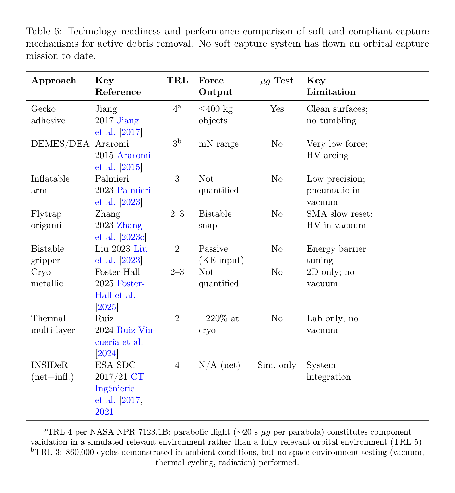
Figure 7: Vacuum-gap electrostatic actuator operating principle (after Sirbu et al. 2025 Sîrbu et al. [2025]). (a) In terrestrial operation, vacuum gaps between electrodes must be maintained against atmospheric pressure, requiring a vacuum pump. (b) In space, the ambient vacuum provides the functional dielectric gap directly, eliminating the pump and enabling higher bandwidth (>100 Hz) at extremely low mass (0.7 g, >4 N, specific power 614 W/kg).
The results establish three design rules for space IEAP deployment:
-
Use ionic liquid electrolytes: IEAP types employing ionic liquid (IL) electrolytes (EMIBF₄, EMITF, EMITFSI) showed no notable degradation under vacuum or cryogenic conditions. Aqueous IPMC actuators (Type A) dry out in vacuum, requiring encapsulation for space use.
-
Provide UV shielding for external applications: UV irradiation destroys PEDOT and PEO-based IEAP materials via photo-oxidation. This is the primary space environment threat. Materials using carbonaceous or conducting polymer electrodes with ionic liquid electrolytes (Types B, C, G) survived UV testing with no notable effect.
-
Plan for cryogenic dormancy: All tested IEAP types survived cryogenic storage (77 K for 2 weeks, 4.22 K for 15 minutes) and recovered full functionality upon warming—the materials cannot operate while frozen but survive and revive Punning et al. [2014].
A counter-intuitive finding is that X-ray radiation initially increases IEAP performance through radiation-induced doping of conducting polymer electrodes, an effect that normalizes within a few actuation cycles Punning et al. [2014]. The force output of current IEAPs remains in the low-millinewton range, limiting applications to sensing-adjacent tasks and micro-manipulation.
7.4 Tendon-Driven Continuum Manipulators
Tendon-driven continuum manipulators represent the highest-force soft actuation approach compatible with space constraints. NASA's Tendril robot (Mehling et al., 2006) established the heritage origin: a 1:1000 aspect-ratio inspection robot designed for confined-space inspection inside the Space Shuttle external tank Mehling et al. [2006]. The Tendril architecture—multiple antagonistic tendons routed along a compliant backbone—provides both the force density and bandwidth necessary for structural manipulation tasks.
Ouyang et al. proposed a hybrid rigid-continuum dual-arm space robot combining a rigid primary arm for strength and reach with a continuum secondary arm for dexterity and compliance Ouyang et al. [2021]. The Generalized Jacobian Matrix analysis demonstrated coordinated motion planning for free-floating operations, establishing the mathematical framework for hybrid architectures where inflatable continuum arms complement rigid primary manipulators.
For space-compatible tendon routing, MoS₂ solid lubricant enables vacuum-compatible sliding contacts, addressing the lubrication challenge that would otherwise limit tendon-driven systems to short operational lifetimes Ruiz Vincuería et al. [2024]. The primary limitation of tendon-driven approaches is that routing tendons over long lengths (>1 m) introduces increasing friction and hysteresis, requiring careful mechanical design.
7.5 Shape Memory Alloys for Deployment
Shape memory alloys (SMAs), principally NiTi (Nitinol), have the highest flight TRL (8–9) among actuator technologies applicable to soft inflatable systems, though primarily for one-shot deployment rather than cyclic actuation. Nitinol achieves up to 10% recoverable strain and cycle life up to 600,000 activation cycles under controlled conditions Costanza and Tata [2020]. Space heritage includes Mars Pathfinder deployment hinges, numerous CubeSat solar array release mechanisms, and ESA satellite solar array root hinges Costanza and Tata [2020], Blanc et al. [2013].
For inflatable structures specifically, the critical limitation of SMA is its slow cooling rate in the vacuum thermal environment. Without convective cooling, SMA actuators rely on radiative heat transfer alone, limiting cyclic actuation frequency to well below 1 Hz for typical element sizes. This effectively restricts SMA to single-deployment or low-frequency repositioning applications in space.
An emerging application combines SMA with inflatable structures: Patel et al. developed an analytical framework for SMA-based rigidisation of inflatable toroidal structures, where NiTi wires embedded in the inflatable wall contract upon heating to lock the deployed geometry Patel et al. [2024]. This represents a potential fourth rigidisation approach beyond the three families established by Cadogan and Scarborough Cadogan and Scarborough [2001], though it remains at the analytical stage (TRL 2–3).
7.6 Jamming in Vacuum: A Novel Opportunity
Variable stiffness by granular or layer jamming presents a counter-intuitive advantage in the space environment that has not been previously identified in the literature. In terrestrial soft robotics, jamming requires a dedicated vacuum pump to evacuate the jammed medium's enclosure, with external atmospheric pressure (∼101 kPa) providing the confining force Fitzgerald et al. [2020]. Zhang et al. noted that jamming structures are "more likely to be used in soft space robots because of scalability, easy fabrication, and low cost" Zhang et al. [2023d], but did not explore the vacuum-specific advantage.
In the space environment, this constraint inverts: the ambient vacuum of LEO (∼10⁻⁷ Pa) serves as the external confining medium, while an inflatable structure's internal pressurization (∼100 kPa) provides the pressure differential across the membrane wall. A sealed jamming structure integrated into or attached to a pressurised inflatable therefore achieves stiffness modulation without any vacuum pump—a simplification unavailable on Earth. Layer jamming, which achieves stiffness ratios exceeding 25:1 in terrestrial systems Fitzgerald et al. [2020], could be particularly well-suited for variable-stiffness robotic elements embedded in inflatable arms.
Figure 8: Jamming-in-vacuum principle for variable stiffness in space. (a) Terrestrial configuration: a vacuum pump evacuates the sealed granular membrane, and atmospheric pressure (∼101 kPa) provides the external confining force that locks the particles. (b) Space configuration: the ambient space vacuum provides external confining pressure directly; the internal pressurisation of the host inflatable structure provides the pressure differential. The vacuum pump is eliminated, and the stiffness transition from compliant to rigid is achieved passively.
The primary engineering challenges are: (1) selecting space-compatible granular media that do not outgas (candidates include hollow glass microspheres and sintered ceramic granules); (2) maintaining gas-tight seals over mission duration against micrometeoroid puncture; and (3) characterising friction behaviour of jammed interfaces in vacuum, where the absence of adsorbed water layers may alter surface friction coefficients. This insight represents a logical deduction from known physics and inflatable structure operating principles, and requires experimental validation—a 5-year research priority identified in Section 13.3.
7.7 Sealed Pneumatic Actuation in Space
The opening constraint of this section—that ultrahigh vacuum eliminates ambient pressure support for unsealed pneumatic systems—does not preclude sealed pneumatic actuators that carry their own gas supply. BEAM itself is the supreme example of a sealed pneumatic structure in space. Ataka et al. Ataka et al. [2020] demonstrated model-based pose control of a pneumatic eversion robot with variable stiffness that is directly relevant to inflatable continuum manipulators for space inspection tasks. Eversion robots, which navigate their environment through growth by turning inside-out Hawkes et al. [2017], are particularly promising for space applications because the growth mechanism inherently manages the gas supply within the extending structure.
Sealed pneumatic actuation with onboard gas storage is viable for missions where the total number of actuation cycles is bounded (limiting gas consumption) or where the inflatable structure's own pressurisation system can serve as the gas source. The mass penalty of gas storage—approximately 0.5–2 kg per litre at 200 bar, depending on tank technology—makes this approach less competitive for sustained cyclic actuation than electrical alternatives, but appropriate for deployment and one-shot or low-cycle capture operations.
7.8 Electroadhesion and Magnetic Actuation: Emerging Approaches
Two additional actuation families, while not yet proposed for space inflatable systems, merit assessment for completeness.
Electroadhesion (electrostatic adhesion to a target surface) differs from the vacuum-gap actuators of Section 7.2 in operating principle: Coulombic attraction to an external target surface rather than internal gap zipping. Guo et al. Guo et al. [2020] demonstrated electroadhesion pads integrated with soft robotic grippers for manipulation of non-cooperative surfaces, achieving adhesion pressures of 1–5 kPa on conductive substrates. For debris capture on metallic spacecraft surfaces, electroadhesion offers a contactless-force alternative to mechanical grasping. The primary space qualification gaps are dielectric breakdown in partial vacuum (outgassing-induced), surface contamination from space debris, and radiation degradation of the dielectric layer.
Magnetic soft actuators with programmed 3D magnetisation profiles Kim et al. [2018] represent a fundamentally different approach that avoids the vacuum and temperature limitations of pneumatics and elastomers. While not yet proposed for space, magnetic actuation in the field-free environment of orbit would require onboard field sources (permanent magnets or electromagnets), adding mass but eliminating the outgassing and embrittlement concerns of polymer-based actuators. This approach remains at TRL 2 for space applications.
Table 14 presents a comparative assessment of the nine actuation technologies assessed for inflatable space systems.
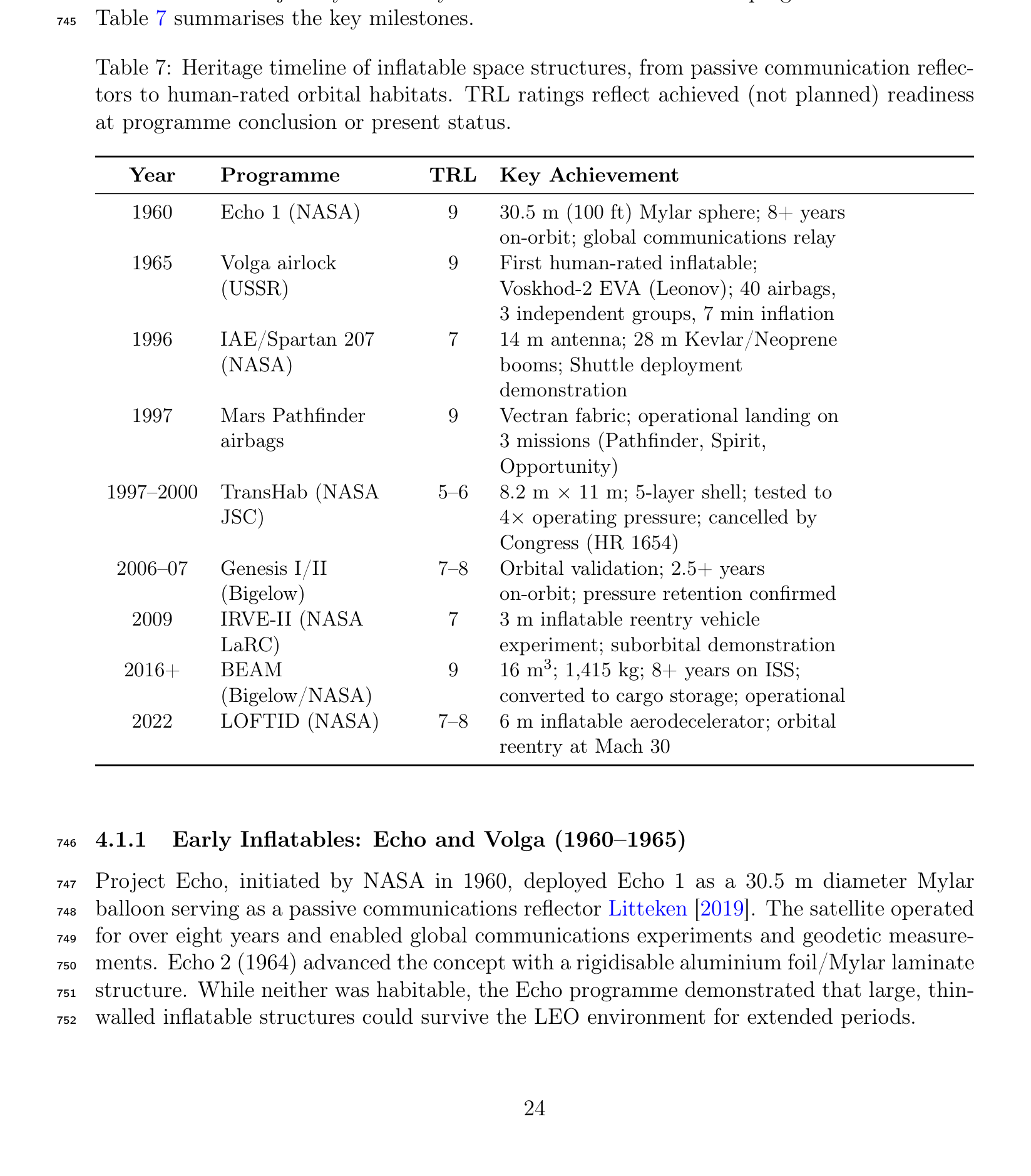
Figure 9: Comparative assessment of actuation technologies for soft inflatable space systems across five performance dimensions: space TRL, force output, bandwidth, vacuum compatibility, and mass efficiency. Ratings on a 0–10 scale follow the rubric in Table 15 and reflect the combined evidence from literature reviewed in Sections 7.1–7.8. Vacuum-gap electrostatic actuators Sîrbu et al. [2025] and jamming Fitzgerald et al. [2020] score highest on vacuum compatibility, reflecting the "vacuum as enabler" paradigm shift.
Table 14: Actuator technology comparison for soft inflatable space systems.
| Technology | Force | Speed | Mass | TRL (Space) | Critical Space Gap |
|---|---|---|---|---|---|
| DEA/DEMES | 0.8–2.2 mN | ∼1 Hz | <0.65 g | 3–4 | UV, outgas., low force |
| Vacuum-gap electrost. | >4 N | >100 Hz | 0.7 g | 3–4 | Radiation, thermal |
| IL-IEAP (types B,C) | Very low | Medium | Excellent | 3–4 | UV (shield), frozen op. |
| Tendon-driven | High | High | Good | 5–6 | Long-path friction |
| SMA (one-shot) | Medium | Slow | Low | 8–9 | Slow cooling, fatigue |
| Jamming (layer) | Stiffness only | Medium | Good | 2–3 | Unvalidated in vacuum |
| Sealed pneumatic | High | Medium | Mod. (gas) | 4–5 | Gas supply mass |
| Electroadhesion | 1–5 kPa | Fast | Low | 2–3 | Surface contam., diel. brkdn |
| Magnetic (programmed) | Medium | Fast | Mod. (magnet) | 1–2 | Requires onboard field |
Table 15: Scoring rubric used for the actuation taxonomy in Figure 9. Intermediate scores are assigned by interpolation within each band and by engineering judgement where the literature reports qualitative rather than numerical performance.
| Score | Space TRL | Force output | Bandwidth | Vacuum compatibility | Mass efficiency |
|---|---|---|---|---|---|
| 0–2 | 1–2 | < 1 mN | < 0.1 Hz | Earth-atmosphere required | > 5 g/N |
| 3–5 | 3–4 | 1 mN–0.1 N | 0.1–10 Hz | Sealed or shielded tolerance | 1–5 g/N |
| 6–8 | 5–7 | 0.1–10 N | 10–100 Hz | Open vacuum compatible | 0.1–1 g/N |
| 9–10 | 8–9 | > 10 N | > 100 Hz | Vacuum improves performance | < 0.1 g/N |
8 State of the Art: Sensing and Structural Health Monitoring
Structural health monitoring (SHM) for inflatable space structures must address three simultaneous requirements: detection of micrometeoroid and orbital debris (MMOD) impacts that may compromise pressure integrity, continuous monitoring of creep deformation in restraint layers under sustained pressure loading, and shape sensing for actively controlled inflatable manipulators. Fibre Bragg Grating (FBG) sensors have emerged as the leading technology platform for all three functions, with a coherent maturation pathway from rigid spacecraft heritage through soft actuator integration to inflatable habitat application.
8.1 Fibre Bragg Grating Sensors: From Proba-2 to Inflatable Webbing
The FBG sensing principle—wavelength-selective reflection from a periodic refractive index modulation inscribed in a fibre core—enables wavelength-division multiplexing (WDM) and time-division multiplexing (TDM) of large sensor arrays on a single fibre strand. A single fibre can carry 100+ independent FBG sensors, each at a distinct Bragg wavelength, providing distributed strain and temperature measurement with no electrical connections at the measurement points McKenzie et al. [2021]. Temperature sensitivity is approximately 10 pm/°C in the 1500–1600 nm wavelength range.
ESA's 20+ year investment in fibre optic sensing for spacecraft culminated in the Fiber Sensor Demonstrator (FSD) aboard Proba-2, launched in November 2009—the first fibre optic sensor network demonstrated in the space environment McKenzie et al. [2021]. The FSD incorporated 12 temperature sensors, a high-temperature thruster sensor, and a xenon tank pressure sensor, establishing TRL 7–8 for FBG technology on rigid spacecraft platforms. Radiation tolerance of appropriately selected fibre types (nitrogen-doped, fluorine-doped) has been confirmed through ground testing, with Type II and Type III FBGs showing the highest radiation hardness Morana et al. [2022], Baba et al. [2025].
The critical transition from rigid spacecraft to inflatable structures was demonstrated by Bally Ribbon Mills (BRM) and Luna Innovations under a NASA SBIR program Bally Ribbon Mills and Luna Innovations [2020]. High-Definition Fibre Optic Sensing (HD-FOS) elements were woven directly into Vectran structural restraint webbing during the manufacturing process—not bonded after fabrication. Testing on 0.61 m and 2.74 m (1/3-scale) inflatable habitat test articles at NASA Johnson Space Center demonstrated detection of:
- Creep deformation under sustained pressure loading
- Internal pressure changes during inflation and operational cycling
- Micrometeoroid impact events (confirmed via hypervelocity impact testing on inflated articles)
The partnership included NASA, Sierra Nevada Corporation, ILC Dover, BRM, and Luna Innovations, targeting applications for the Lunar Gateway and Mars transit habitats Bally Ribbon Mills and Luna Innovations [2020]. However, these results have been reported only in technical briefs and SBIR documentation, not in peer-reviewed publications—a gap that limits independent assessment of sensitivity metrics, minimum detectable impact size, and long-term reliability.
The TRL assessment for FBG sensing across application domains is:
- FBG on rigid spacecraft: TRL 7–8 (Proba-2 FSD flight heritage, 2009)
- FBG in Vectran restraint webbing: TRL 4–5 (NASA JSC ground testing, 0.61 m and 2.74 m articles)
- FBG in operational inflatable habitat (flight): TRL 2–3 (not yet demonstrated)
8.2 Multicore Fibre Optic Shape Sensing
For soft actuator shape sensing, Galloway et al. demonstrated the first integration of a monolithic multicore Fibre Optic Shape Sensor (FOSS) into a fibre-reinforced soft pneumatic actuator Galloway et al. [2019]. The multicore fibre contains multiple sensing cores within a single cladding, enabling three-dimensional shape reconstruction from differential curvature measurements without requiring multiple separate fibre installations. Key results include a mean tip position error of 0.64 mm, successful reconstruction of six distinct planar shape profiles, and simultaneous detection of collision events, environmental shape changes, and material stiffness variations within a single sensing modality.
Table 16: Sensing technology comparison for inflatable structural health monitoring.
| Technology | Accuracy | Channels/Fiber | Space Heritage | Demo Scale | TRL |
|---|---|---|---|---|---|
| FBG (rigid s/c) | ±10 µε / ±1°C | 100+ | Proba-2 (2009) | Satellite | 7–8 |
| FBG (Vectran webbing) | Creep/MMOD det. | Multiple | JSC ground | 2.74 m | 4–5 |
| Multicore FOSS | 0.64 mm tip | Multicore | Lab only | Actuator | 3–4 |
| DFOS (Rayleigh) | ±1 µε | Continuous | Lab only | m-scale | 2–3 |
| Capacitive (stretch.) | ±5% strain | Per-sensor | Lab only | cm-scale | 2–3 |
| Resistive (fabric) | ±2% strain | Per-sensor | Lab only | cm-scale | 2–3 |
| Piezoelectric (PVDF) | Impact detection | Array | Lab only | Panel | 2–3 |
The field has advanced significantly since Galloway's initial demonstration. Paloschi et al. Paloschi et al. [2021] developed improved 3D shape reconstruction algorithms for multicore optical fibres, comparing transformation matrix approaches with Frenet-Serret equations for real-time applications and demonstrating that transformation matrix methods achieve superior accuracy for large-curvature deformations characteristic of soft actuators. Sefati et al. Sefati et al. [2021] demonstrated data-driven shape sensing of continuum manipulators using FBG sensors, achieving 1.22 mm distal-end position error without requiring sensor calibration—an approach relevant to the tendon-driven continuum arms discussed in Section 7.4. These advances collectively bring multicore FOSS from a proof-of-concept to a viable shape sensing modality for soft space manipulators, though the interrogator hardware miniaturisation and radiation tolerance gaps remain.
The multicore FOSS approach offers two advantages over distributed single-core FBG arrays for soft structure applications. First, the monolithic construction eliminates the need for multiple fibre routing paths through complex soft geometries. Second, the differential curvature measurement provides inherent common-mode rejection of temperature-induced wavelength shifts, improving strain measurement accuracy in the thermally variable space environment. The primary barriers to space qualification are the mass and power requirements of the multicore FOSS interrogator (readout) hardware, which has not yet been miniaturized for spacecraft integration, and the radiation tolerance of the multicore fibre itself, which has not been characterised.
For broader context, Ramakrishnan et al. Ramakrishnan et al. [2016] provide a comprehensive review of FBG sensors for structural health monitoring across aerospace applications, confirming that FBG-based SHM is the most mature fibre optic sensing technology for spacecraft structures and identifying the key challenges for transitioning from rigid to flexible substrates.
8.3 Capacitive, Resistive, and Alternative Soft Sensors
While FBG sensors dominate the space-qualified sensing landscape, alternative soft sensing technologies merit assessment for completeness. Zhang et al. Zhang et al. [2023a] devote significant attention to stretchable capacitive sensors, resistive fabric sensors, and liquid metal strain sensors for soft space robots. The advantages of these technologies include: no requirement for specialised interrogator hardware (unlike FBG, which requires wavelength-swept laser sources), simpler integration into soft structures via printing or embedding, and lower per-sensor cost. However, for space applications, three significant limitations arise:
-
Electromagnetic interference (EMI) sensitivity: Capacitive and resistive sensors operate in the electrical domain and are vulnerable to the charged particle environment of LEO, solar radio bursts, and EMI from onboard electronics. FBG sensors, operating in the optical domain, are inherently immune to EMI—a decisive advantage for spacecraft.
-
Radiation vulnerability: Liquid metal sensors (e.g., eutectic gallium-indium, EGaIn) and conductive polymer sensors have not been characterised for radiation tolerance. Ionising radiation can alter the resistivity of conductive polymers and the wetting properties of liquid metals, degrading sensor calibration over mission-duration timescales.
-
Multiplexing limitations: A single optical fibre can carry 100+ independent FBG sensors via wavelength-division multiplexing; achieving comparable channel density with electrical sensors requires extensive wiring harnesses that add mass and failure modes to flexible structures.
For inflatable habitat applications, capacitive pressure sensors could complement FBG strain sensors by providing direct pressure measurement at locations inaccessible to fibre routing. For soft robotic manipulators, resistive bend sensors offer simplicity advantages for prototype development, though FBG remains the preferred technology for flight systems.
8.4 Distributed Fibre Optic Sensing: Rayleigh and Brillouin Scattering
Distributed fibre optic sensing (DFOS) by Rayleigh or Brillouin scattering provides continuous strain and temperature profiles along the entire fibre length, rather than at discrete FBG grating locations. Rayleigh-based DFOS (e.g., Luna Inc. ODiSI platform) achieves spatial resolution of approximately 0.65 mm with strain resolution better than ±1 µε, while Brillouin-based systems provide sensing over distances up to 100 km at reduced spatial resolution (typically 0.5–1 m). For inflatable habitats with large membrane areas requiring continuous monitoring (rather than point-by-point FBG interrogation), DFOS offers the potential for comprehensive strain mapping of the entire restraint layer from a single fibre installation.
The principal barriers to space deployment of DFOS are: (i) interrogator size, mass, and power (current laboratory DFOS systems exceed 10 kg and 50 W, compared to <2 kg and <10 W for space-grade FBG interrogators); (ii) sensitivity to fibre bending loss, which is exacerbated by the tight bend radii in folded inflatable structures during stowage; and (iii) the absence of any space-environment characterisation data. DFOS is assessed at TRL 2–3 for space inflatable applications, but its unique capability for continuous spatial coverage makes it a high-priority development target for large-scale habitat SHM systems.
8.5 Distributed Impact Detection
The Distributed Impact Detection System (DIDS) installed on BEAM represents the highest-TRL implementation of impact sensing for inflatable habitats. DIDS uses distributed sensors to detect and locate MMOD impacts on the inflatable shell, providing real-time structural integrity monitoring.
Beyond the BEAM DIDS, two emerging approaches extend impact detection capabilities. The BRM/Luna FBG-in-Vectran-webbing system described in Section 8.1 detected hypervelocity impacts during ground testing, with the woven integration providing inherent coverage of the restraint layer structural grid Bally Ribbon Mills and Luna Innovations [2020]. Separately, White et al. demonstrated on-demand fabrication of PVDF-trFE piezoelectric sensors via in-space manufacturing techniques, enabling the production of impact detection arrays directly on deployed inflatable structures White et al. [2024]. This approach could address the challenge of instrumenting structures that are too large or complex to pre-instrument before launch.
Li et al. proposed a complementary SHM approach based on low-frequency vibration response characterisation of pressurised inflatable structures, where changes in modal frequencies indicate structural degradation Li et al. [2022b]. This global monitoring approach could complement the local sensing provided by FBG arrays, together forming a hierarchical SHM architecture: global vibration monitoring for overall structural health assessment, and local FBG sensing for precise damage location and magnitude quantification.
The pathway from current demonstrated capabilities to a flight-qualified inflatable SHM system requires: (1) formal peer-reviewed publication of the BRM/Luna FBG-in-webbing results with full sensitivity characterisation; (2) space qualification of FOSS interrogator hardware (mass, power, radiation tolerance); (3) development of data fusion algorithms combining local FBG and global vibration sensing; and (4) a flight demonstration, potentially as an ISS external payload experiment, to bridge the TRL 4–5 to TRL 7–8 gap.
9 State of the Art: Power Systems for Large Inflatables
The integration of electrical power generation with inflatable space structures is a critical enabling challenge for large deployable platforms. Unlike rigid spacecraft, where solar arrays are mechanically decoupled from the primary structure, inflatable systems present the possibility—and the engineering challenge—of co-locating photovoltaic generation on the deployable membrane itself. This section reviews the flexible solar array landscape, the singular attempt at inflatable-power integration (PowerSphere), and energy storage considerations for mission architectures ranging from 100 m-class debris shields to inflatable habitats.
9.1 Flexible Solar Array Landscape: ROSA to Perovskite
The current state of the art in flexible solar arrays for space is defined by the Roll-Out Solar Array (ROSA), which achieved TRL 9 via ISS flight demonstration in June 2017 as part of the STP-H5 experiment Spence et al. [2018]. The demonstration unit (5.40 m × 1.67 m) deployed successfully using stored strain energy in carbon-fibre-reinforced polymer (CFRP) slit-tube booms, requiring no motors. The subsequent production variant, iROSA, scaled to 6 m × 13.7 m wings generating over 28 kW per wing at beginning of life with XTJ Prime triple-junction cells at 30.7% efficiency. Six iROSA wings installed on the ISS between 2021 and 2023 added over 120 kW of generation capacity. At system level (blanket plus booms, excluding spacecraft attachment hardware), ROSA achieves a specific power exceeding 100 W/kg—approximately 3.7× the legacy ISS silicon rigid-panel arrays at ∼27 W/kg Spence et al. [2018], Yan et al. [2025]. Critically, however, ROSA's flexible photovoltaic blanket is deployed on rigid composite booms; the deployment mechanism is structurally distinct from inflatable substrate concepts.
Beyond ROSA, three deployment architectures compete for next-generation high-power arrays Yan et al. [2025]: (i) Z-fold accordion panels on a central mast, representing the ISS legacy approach at TRL 9; (ii) fan-fold blankets on deployable masts, exemplified by China's CST arrays on the Wentian laboratory module (2022), achieving approximately 4× the specific power of rigid baselines; and (iii) roll-out arrays (ROSA/iROSA class). Mega-ROSA and SOLAROSA concepts target 200–500 W/kg for systems exceeding 100 kW, though these remain at TRL 4–5 Yan et al. [2025]. For very large arrays approaching the kilometre scale (Space Solar Power Station concepts), wireless power transmission between modules has been identified as a necessity Yan et al. [2025].
A paradigm shift in flexible photovoltaic technology is emerging from perovskite-based tandem cells. Lang et al. Lang et al. [2020] provided the critical finding that perovskite/CIGS (copper indium gallium selenide) tandem cells are radiation-hard, while perovskite/silicon heterojunction (SHJ) tandems are emphatically not. Under 68 MeV proton irradiation at a fluence of \( 2 \times 10^{12} \) p⁺/cm² (equivalent to over 50 years at ISS altitude), perovskite/CIGS tandems retained approximately 85% of initial power conversion efficiency, whereas perovskite/SHJ devices degraded catastrophically to ∼1% retention due to proton-induced deep trap states in the silicon bottom cell Lang et al. [2020]. The perovskite top cell itself was essentially unaffected, with quasi-Fermi level splitting changing by only 0.004 eV. With active layers only 4.38 µm thick (2.8 mg/cm²), perovskite/CIGS achieves a specific power of 7,400 W/kg at the active-layer level, or 2,100 W/kg when including a 25 µm flexible polyimide substrate Lang et al. [2020]. More recently, Jeong et al. Jeong et al. [2024] demonstrated 23.64% efficient flexible perovskite/CIGS tandems surviving 100,000 bending cycles with a specific power of approximately 6,150 W/kg at the cell level.
These figures represent a 10–60× improvement over ROSA's system-level specific power, though the comparison requires careful attention to system boundaries: cell-only figures exclude interconnects, encapsulant, wiring harness, and structural substrate, which collectively reduce specific power by a factor of 3–6× at the system level. Table 17 summarises the specific power versus TRL landscape across flexible photovoltaic technologies.
9.2 The Inflatable-Power Integration Gap: PowerSphere and Beyond
The most direct attempt to integrate thin-film photovoltaics with an inflatable deployable structure was NASA's PowerSphere programme (2004–2009), led by ILC Dover (structure), NASA Glenn Research Center (cells), and Sandia National Laboratories (interconnects) Cadogan et al. [2006b], Simburger et al. [2005]. The PowerSphere Engineering Development Unit was a 0.6 m diameter UV-rigidisable inflatable geodetic sphere clad with thin-film amorphous silicon (a-Si) solar cells on a polyimide substrate. The complete system comprised a 1 kg PowerSphere subsystem mounted on a 3 kg bus, with 15 cells per hemisphere (9 hexagonal, 6 pentagonal) connected via copper wrap-around flex-circuit interconnects that could survive folding during stowage without cracking Cadogan et al. [2006b], Simburger et al. [2005].
Table 17: Specific power versus TRL for flexible photovoltaic technologies for space applications. Cell-only and system-level figures are distinguished where data are available.
| Technology | Specific Power (W/kg) | Efficiency (%) | TRL | Ref. |
|---|---|---|---|---|
| Legacy ISS SAW (rigid) | ∼27 (system) | 14 | 9 | Spence et al. [2018] |
| ATK UltraFlex | ∼150 (system) | 28–30 | 9 | — |
| ROSA/iROSA | >100 (system) | 30.7 | 9 | Spence et al. [2018] |
| Mega-ROSA (target) | >200–400 | 30.7 | 4–5 | Yan et al. [2025] |
| Perovskite/CIGS (25 µm sub.) | 2,100 (cell+sub.) | 19.2 | 3–4 | Lang et al. [2020] |
| Perovskite/CIGS (Kim 2024) | ∼6,150 (cell) | 23.6 | 3–4 | Jeong et al. [2024] |
| PowerSphere (a-Si, measured) | ∼7 (system) | 10 | 4–5 | Cadogan et al. [2006b] |
| PowerSphere (proj. w/ III-V) | ∼85 (projected) | 27–30 | — | Cadogan et al. [2006b] |
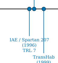
Figure 10: Specific power versus technology readiness level for flexible photovoltaic technologies relevant to inflatable space structures. Marker size indicates cell efficiency. Perovskite-based technologies Lang et al. [2020], Jeong et al. [2024] offer 10–60× improvements over heritage ROSA systems Spence et al. [2018] at the cell level, but remain at TRL 3–4. The green shaded region indicates the target design space for next-generation inflatable-power integration: high specific power (>400 W/kg) at flight-qualified TRL (>6).
The UV-rigidisation mechanism is particularly significant for the survey's themes. Thirty hinges per sphere used S-glass fibre reinforced with ATI-P600-2 UV-curing epoxy (glass transition temperature Tg = 211°C), encapsulated in UV-transparent 1-mil Mylar film. Upon exposure to solar UV radiation (λ < 385 nm) for 10–45 minutes post-deployment, the resin polymerised, converting the inflatable into a self-supporting rigid structure and eliminating the requirement for long-term inflation gas retention Cadogan et al. [2006b]. Inflation was achieved passively through vapour pressure from sublimation powder at approximately 1 psi (∼6.9 kPa).
Thermal cycling tests (−120°C to +80°C, 1000 cycles per NASA specification) demonstrated cell and interconnect survival with less than 2% power degradation, although one of four interconnect coupons failed, prompting the addition of a titanium binder layer as a design modification. Cell interconnect technology was partially validated on the MISSE-5 experiment aboard the ISS Cadogan et al. [2006b]. At 10% a-Si cell efficiency, the 0.6 m prototype generated approximately 29 W at design point, yielding a system specific power of ∼7.25 W/kg. With projected III-V triple-junction cells at 27–30% efficiency, the concept was estimated to reach ∼85 W/kg.
The PowerSphere programme reached TRL 4–5 but never flew. Planned missions—the PowerSphere Flight Experiment and PSIREX (Pico Satellite Inflatable Reflector Experiment)—were not implemented, and the programme appears inactive since the final publication by Curtis et al. in 2007 on thermal cycling results Curtis et al. [2007]. No successor programme integrating thin-film photovoltaics with inflatable structure deployment has been identified. This represents a critical gap: ROSA (TRL 9) demonstrates that flexible photovoltaic blankets function reliably in space, and PowerSphere (TRL 4–5) demonstrated that cells can survive fold/deploy on an inflatable substrate, but nobody is currently pursuing inflatable-integrated photovoltaics. A revival of the PowerSphere concept using modern perovskite/CIGS cells—which offer 200–300× higher specific power than the original a-Si cells and validated radiation hardness Lang et al. [2020]—represents a logical and compelling research direction.
9.3 Energy Storage: Li-ion, RFC, and Mission-Dependent Selection
Energy storage for large inflatable structures follows established space heritage, with technology selection driven primarily by eclipse duration and mission architecture. The current standard is lithium-ion, with state-of-the-art cell-level specific energy of 200–300 Wh/kg and system-level (including battery management, thermal control, and structure) of 100–160 Wh/kg Sharma and Santasalo-Aarnio [2025]. The ISS lithium-ion upgrade programme (2017–2021), replacing nickel-hydrogen (Ni-H₂) with 24 lithium-ion Orbital Replacement Units (ORUs) at 4 kWh each, provides direct heritage for large-structure lithium-ion energy storage.
For a 100 m-class inflatable debris shield in LEO (90-minute orbit, 36-minute eclipse), the power demand is driven by supporting subsystems rather than the passive membrane itself. Station-keeping via electric propulsion dominates at 1–50 kW depending on orbit and attitude strategy (Section 11.3); attitude control, telemetry, and sensors add 1–7 kW. A total system power demand in the range of 2–50 kW is appropriate, requiring 4–40 kWh of eclipse energy storage—translating to 25–250 kg of lithium-ion battery mass at 160 Wh/kg system level. This is a non-trivial but manageable fraction of the estimated 5,000 kg total system mass.
For missions requiring extended eclipse storage—notably lunar surface operations (354-hour lunar night) or deep-space transit—regenerative fuel cells (RFCs) offer 400–1,000 Wh/kg at system level but remain at TRL 5–6 for space applications Sharma and Santasalo-Aarnio [2025]. Supercapacitors (5–15 Wh/kg) are poorly suited for eclipse energy storage but may serve pulsed-load applications such as electric propulsion ignition or deployment actuators. Table 18 summarises the energy storage technology comparison.
Table 18: Energy storage technologies for large inflatable space structures.
| Technology | Sp. Energy (Wh/kg) | Cycle Life | TRL | Best Use Case |
|---|---|---|---|---|
| Li-ion (cell) | 200–300 | >30,000 | 9 | LEO eclipse storage |
| Li-ion (system) | 100–160 | >30,000 | 9 | LEO eclipse storage |
| Ni-H₂ (legacy) | 30–60 | >40,000 | 9 | Heritage only |
| RFC (H₂/O₂) | 400–1,000 | — | 5–6 | Lunar night, deep space |
| Supercapacitor | 5–15 | >500,000 | 7 | Pulsed loads |
| RTG | N/A | — | 9 | No-sun environments |
10 State of the Art: Thermal Management
Thermal management for inflatable space structures presents unique challenges that stem from the fundamental nature of the structural material: thin fabric membranes offer minimal thermal mass, poor through-thickness conductivity, and large surface area-to-volume ratios. These characteristics amplify the orbital thermal cycling environment and demand thermal control approaches that are compatible with the fold/deploy lifecycle, vacuum exposure, and the mechanical flexibility of the host structure. This section reviews established approaches (multi-layer insulation, loop heat pipes), the JWST sunshield as a large-area deployable thermal barrier precedent, and emerging technologies (variable emissivity coatings, phase change materials) that offer particular promise for inflatable applications.
10.1 Multi-Layer Insulation for Inflatable Shells
Multi-layer insulation (MLI) is the primary passive thermal control technology for spacecraft and achieves effective emittance εeff = 0.005–0.05 for 10–40 layer blankets Gilmore [2002], Finckenor and Dooling [1999]. For conventional rigid spacecraft, MLI is draped over external surfaces with controlled layer separation maintained by low-conductance spacers (typically Dacron netting). For inflatable structures, MLI integration is more complex: the insulation must survive folding, accommodate deployment kinematics, and maintain layer separation without rigid structural support.
The TransHab/BEAM heritage shell architecture represents the current standard for inflatable habitat thermal design Kennedy [2002], Valle et al. [2019a]. In this architecture, MLI forms the outermost thermal protection sub-assembly of a five-layer softgoods stack, ordered (outer to inner) as: (1) BETA cloth exterior for atomic oxygen protection; (2) nylon-reinforced double-aluminised Mylar/Kapton MLI layers with perforated inner surfaces for venting during deployment; (3) Nextel/Kevlar stuffed-Whipple MMOD shield; (4) Vectran restraint layer carrying hoop and axial pressure loads; and (5) multi-redundant gas-tight bladder. The MLI sub-assembly in TransHab comprised over 20 individual reflector layers with effective emittance on the order of 0.015–0.05 Finckenor and Dooling [1999].
BEAM's on-orbit thermal performance has been characterised as "more benign than predicted" NASA Johnson Space Center [2017], an observation attributed to the additional insulation provided by folded softgoods layers that act as low-conductance barriers even when not specifically designed as MLI. This finding has positive implications for inflatable structure design: the inherent multi-layer nature of the fabric wall stack provides a degree of passive thermal buffering beyond that of the dedicated MLI layers alone.
10.2 The JWST Sunshield as Deployable Thermal Barrier Precedent
The James Webb Space Telescope (JWST) sunshield is the largest deployed thermal barrier ever flown and provides the benchmark for what large-area passive thermal isolation can achieve Arenberg et al. [2016]. At 21.2 m × 14.2 m (approximately 300 m²), the kite-shaped sunshield comprises five layers of Kapton E polyimide membrane: Layer 1 (sun-facing) at 50 µm thickness, Layers 2–5 at 25 µm. All layers are coated with 100 nm aluminium on both sides for reflectivity; Layers 1 and 2 additionally carry 50 nm doped silicon on the sun-facing surface for enhanced emissivity and electrostatic discharge grounding.
The thermal performance is extraordinary: the sun-facing side of Layer 1 reaches approximately +110°C while the telescope-facing side of Layer 5 operates at −233°C—a gradient of 343°C across five layers. Incoming solar power of approximately 200–250 kW is attenuated to ∼23 mW transmitted to the cold side, an attenuation ratio of approximately 10⁶:1 Arenberg et al. [2016]. This performance is achieved through the V-groove geometry: angled layers radiate inter-layer thermal energy sideways to deep space through the vacuum gaps between membranes.
However, the JWST sunshield is not an inflatable structure. Layer separation is maintained by six rigid spreader bars, with centre gaps of ∼25–50 mm expanding to ∼250 mm at the edges. The deployment system required 139 of JWST's 178 release mechanisms, 400 pulleys, 90 cables (∼0.5 km total), 8 motors, and 70 hinges Arenberg et al. [2016]. Table 19 compares the JWST sunshield and TransHab shell architectures.
Table 19: JWST sunshield versus TransHab inflatable shell comparison.
| Feature | JWST Sunshield | TransHab Shell |
|---|---|---|
| Primary function | Thermal isolation | Structural + MMOD + thermal |
| Layer count | 5 membranes | 5 sub-assemblies (60+ layers) |
| Layer material | Kapton E (all 5) | Vectran, Kevlar, Nextel, Mylar |
| Structural role | None (spreader bars) | Vectran restraint carries pressure |
| Energy attenuation | 10⁶:1 | ∼150°C gradient |
| Deployment | 139 mechanisms, 8 motors | Inflation pressure |
| Deployed area | 300 m² | 220 m² (cylinder) |
It should be noted that JWST operates at the Sun-Earth L2 point, not in LEO—the thermal environment is fundamentally different (no orbital cycling, no atmospheric drag, no atomic oxygen), and this limits the direct applicability of JWST thermal performance numbers to LEO inflatable structures. Nevertheless, for inflatable debris shields or large-area thermal barriers, the JWST heritage demonstrates that multi-layer Kapton stacks achieve extreme thermal gradients at 20+ metre scales. Adapting this concept to a fully inflatable deployment mechanism—replacing rigid spreader bars with inflation-maintained layer separation—remains an open engineering challenge. A hybrid approach combining inflatable outer layers with rigid-bar-maintained inner separation represents a plausible intermediate architecture.
10.3 Variable Emissivity Coatings and Smart Radiators
Variable emissivity materials (VEMs) offer "electronic louver" functionality for dynamic thermal regulation without mechanical moving parts—a capability uniquely suited to large inflatable surfaces where conventional mechanical louvers are impractical due to mass, complexity, and incompatibility with membrane substrates. Two technology families have received sustained development: passive thermochromic coatings and active electrochromic devices.
Among passive thermochromic approaches, vanadium dioxide (VO₂) based coatings are technically most advanced. Kim et al. Kim et al. [2019] performed the first direct calorimetric measurement of a VO₂-based switchable radiator in a simulated space environment (vacuum 10⁻⁷ Torr, cold block at 108 K). Their multilayer structure—Si substrate / VO₂ (40–100 nm) / BaF₂ dielectric spacer (1,500 nm) / Au back reflector (200 nm)—operates as a Fabry-Pérot resonant absorber. In the low-temperature insulating state (T < 340 K), hemispherical emissivity is εL = 0.16; above the phase transition (T > 340 K, metallic VO₂), εH = 0.51, yielding ∆ε = 0.35. The practical consequence is a net radiated power difference of 480 W/m² between 300 K and 373 K—a factor of 7× in radiative cooling capacity Kim et al. [2019]. The silicon substrate provides an incidental benefit: protection of the VO₂ film from atomic oxygen erosion, addressing a known degradation mechanism. An earlier design by Hendaoui et al. Hendaoui et al. [2013] achieved a higher normal emissivity swing of ∆ε = 0.49 but without the atomic oxygen protection.
The sole flight-demonstrated variable emissivity technology is the EclipseVED™ electrochromic coating (Ashwin-Ushas Corporation), flown on the MidSTAR-1 satellite in 2007, achieving TRL 7–8. EclipseVED operates by applying a low voltage (1–3 V) to an electrochromic polymer film, switching emissivity across the range ε ≈ 0.19–0.90 in the 8–12 µm thermal infrared band. It requires no mechanical actuators, making it compatible with large-area application including inflatable surfaces. The principal limitation is the requirement for a thin-film conductor and electrical interconnects across the deployed area—a tractable but non-trivial integration challenge for inflatable structures.
Table 20 compares variable emissivity technologies.
Table 20: Variable emissivity coating technologies for spacecraft thermal control.
| Technology | ∆ε | T_switch | Power | TRL | Flight Heritage |
|---|---|---|---|---|---|
| VO₂ (Kim 2019) | 0.35 (hemi.) | 67°C | Zero | 3–4 | None |
| VO₂ (Hendaoui 2013) | 0.49 (normal) | 67°C | Zero | 3 | None |
| EclipseVED (electrochromic) | ∼0.71 | Voltage ctrl | 1–3 V | 7–8 | MidSTAR-1 (2007) |
| MEMS louvers | ∼0.8 (eff.) | Bimetal | Zero | 7–8 | Multiple |
For the survey's inflatable structures context, VEMs offer a path to autonomous thermal self-regulation: at high temperature (sunlit, electronics active), emissivity increases to reject heat; at low temperature (eclipse), emissivity decreases to conserve heat. This self-regulating behaviour eliminates active heaters in many scenarios, reducing power demand on power-constrained large inflatable platforms. The principal barrier to inflatable application is substrate compatibility: VO₂ coatings currently require rigid silicon substrates, while EclipseVED has been demonstrated only on rigid aluminium panels. Developing these technologies on flexible polymer substrates (Kapton, polyimide) is a near-term research priority.
10.4 Loop Heat Pipes for Deployed Structures
Loop heat pipes (LHPs) are the preferred heat transport technology for active thermal systems in space, offering passive capillary-driven two-phase fluid transport with zero pump power, distances up to several tens of metres, and heat loads up to 5+ kW per evaporator Maydanik [2005]. The capillary driving force is generated by a sintered porous wick confined to a compact evaporator body; vapour and liquid travel in separate smooth-wall transport lines. A compensation chamber at the evaporator provides thermal buffering and enables active setpoint control to ±0.5°C via low-power heaters (1–5 W). Working fluids for space include ammonia (−40 to +70°C, the standard), propylene (−60 to +50°C, when ammonia freeze risk exists), and ethane (−100 to +30°C) for cryogenic applications.
LHP spaceflight heritage extends over 35 years, beginning with the Granat astrophysics satellite in 1989 and encompassing over 30 systems flown by 2005 across Russian, American, and European programmes Maydanik [2005]. The Hughes HS-702 communications satellite (1999) demonstrated the first LHP-coupled deployable radiator—the directly relevant precedent for inflatable structures, as the LHP flexible transport lines accommodated the mechanical hinge between the deployed radiator panel and the spacecraft bus. NASA's EOS Terra and Aqua missions, ICESat/GLAS, and Swift/BAT all employed LHP thermal control.
For inflatable habitats, LHPs are the natural technology for transporting waste heat from interior systems (avionics, crew metabolic load) to external deployable radiators. The flexible transport lines can be routed through deployment hinges and accommodate the geometric changes between stowed and deployed configurations. Current single-evaporator LHP systems transport 50–700 W in typical spacecraft configurations, with multi-loop architectures providing aggregate capacities exceeding 10 kW for large platforms. The principal engineering challenge for inflatable integration is the condenser interface: bonding or mechanically attaching the condenser panel to the flexible membrane requires a solution to the rigid-to-flexible interface problem discussed in Section 12.3.
10.5 Phase Change Materials in Fabric Layers: The TRL 2–3 Gap
Phase change materials (PCMs) offer passive thermal buffering by absorbing and releasing latent heat during orbital day/night transitions. For LEO inflatable habitats experiencing 90-minute thermal cycles, the most promising PCM candidates are n-eicosane (melting point 36.4°C, latent heat 247–253 J/g) and n-octadecane (28.2°C, 244 J/g) Diaconu et al. [2024]. PCM-based thermal control for rigid electronics enclosures has extensive spaceflight heritage spanning from Apollo Lunar Roving Vehicle battery management (1971) through Mars rovers (Spirit, Opportunity, Curiosity, Perseverance; TRL 9) and ISS experiments (TRL 5–6) Diaconu et al. [2024].
However, integration of PCMs into flexible fabric layers for inflatable structures—the configuration needed to provide distributed thermal buffering across large membrane areas—remains at TRL 2–3. Five specific technical barriers have been identified:
-
Microgravity containment: Liquid-phase PCM migrates freely in zero-g. Microencapsulation (1–100 µm capsules) addresses this at small scale, but capsule integrity during the fold/deploy lifecycle has not been tested for space-grade materials.
-
Fold/deploy cycling: PCM-loaded fabric must survive hundreds to thousands of fold/deploy cycles without capsule rupture—a requirement with no demonstrated solution in the space-qualified materials literature.
-
Outgassing: PCM solvents and vapour can contaminate optical surfaces (solar cells, sensors). Space-qualified encapsulation that meets ASTM E595 outgassing requirements has not been characterised for PCM-textile systems.
-
Thermal conductivity: Raw paraffin PCMs have thermal conductivity k ≈ 0.2 W/(m·K)—approximately 1,000× lower than aluminium—resulting in slow thermal response. Carbon nanotube or graphene additives can improve conductivity to 1–5 W/(m·K) but at the cost of reduced fabric flexibility and increased mass.
-
Atomic oxygen interaction: PCM capsule shells (typically PMMA or gelatin) may erode under atomic oxygen flux in LEO, releasing PCM material and contaminating the local environment.
Despite these barriers, the potential benefit is substantial. A 1 kg/m² layer of microencapsulated n-eicosane would provide ∼250 J/g × 1,000 g/m² = 250 kJ/m² of thermal storage—sufficient to buffer the first ∼10 minutes of eclipse entry for a membrane with low thermal mass, significantly reducing peak-to-trough temperature excursions. The technology needs a structured development programme analogous to what IRVE provided for flexible thermal protection systems.
11 State of the Art: Attitude and Orbit Control
Attitude and orbit control for large inflatable space structures is dominated by a single overarching challenge: control-structure interaction (CSI). When structural flexibility approaches or overlaps the attitude control bandwidth, conventional rigid-body AOCS designs become inadequate or unstable. For 100 m-class inflatable structures, where the lowest natural frequencies may fall well below 0.1 Hz, CSI is not merely a complication—it is the central design driver. This section reviews the CSI challenge, the theoretical framework of gyroelastic body dynamics, the drag budget for large LEO structures, and the critical gap in AOCS theory for pressure-stabilised membranes.
11.1 Control-Structure Interaction for Flexible Spacecraft
CSI has been studied since the 1970s in the context of large space systems including the Solar Power Satellite concept, the Space Station, and large deployable antennas. For mechanically stiff structures—rigid trusses, mesh antennas, deployable solar arrays—the lowest structural modes typically fall in the 0.1–1 Hz range for 10–30 m scale structures, and structural damping ratios ζ ≈ 0.001–0.005 are small but predictable Angeletti et al. [2022]. The standard approach is modal truncation and notch filtering: identify the structural modes, exclude them from the control bandwidth, and ensure adequate frequency separation between rigid-body and flexible modes.
For inflatable (pressure-stabilised) structures, the CSI problem is qualitatively different in four respects. First, structural stiffness is primarily provided by membrane tension arising from internal pressure (σhoop = pR/t for a cylindrical geometry) rather than material bending stiffness, and this stiffness changes if pressure is lost due to microleaks or thermal cycling. Second, the lowest natural frequencies scale inversely with structure size and can be ≪ 0.1 Hz for 100 m-class structures, potentially falling within the AOCS bandwidth. Third, membranes cannot carry compressive stress—they wrinkle, creating local zones of nonlinear stiffness that invalidate linear modal analysis. Fourth, actuator forces transmitted through a flexible membrane diffuse spatially rather than transmitting cleanly through a rigid structural path, degrading actuator-to-mode coupling. No paper in the published literature explicitly addresses AOCS for pressure-stabilised inflatable structures at the 100 m scale.
Angeletti et al. Angeletti et al. [2022] developed a "minimum complexity" hybrid ODE-PDE model for large flexible spacecraft that provides a useful methodological template: the rigid bus is treated as an ODE system (6 DOF) coupled to the flexible structure as a PDE system (beam/plate). Even a 2-mode truncation captured over 80% of the relevant dynamics for control design. However, this framework assumes conventional bending stiffness and is not directly applicable to pressure-stabilised membranes.
11.2 Gyroelastic Body Theory and Distributed Momentum Management
The theoretical foundation for distributed attitude actuators on flexible structures was established by D'Eleuterio and Hughes in a series of foundational papers D'Eleuterio and Hughes [1984, 1986, 1987]. The 1984 paper introduced the concept of gyricity—the distribution of angular momentum per unit volume embedded within an elastic continuum. The governing equations couple elastic deformation to rigid-body rotation through the gyricity distribution g(x), showing that distributed angular momentum fundamentally modifies elastic wave propagation and natural frequencies. The key theoretical finding is that gyroelastic systems have complex eigenvalues (gyroelastic frequency splitting), providing passive damping-like behaviour without explicit energy dissipation—analogous to Zeeman splitting in quantum mechanics D'Eleuterio and Hughes [1984]. The 1986 companion paper D'Eleuterio and Hughes [1986] derived the modal parameters (complex mode shapes, orthogonality conditions, participation factors) needed for practical numerical analysis, while the 1987 paper D'Eleuterio and Hughes [1987] extended the framework to complete spacecraft systems, treating a vehicle with distributed angular momentum storage as a unified gyroelastic body.
Damaren and D'Eleuterio Damaren and D'Eleuterio [1989] solved the optimal gyricity distribution problem using calculus of variations: the spatial distribution \( g^*(x) \) that minimises a quadratic performance index concentrates angular momentum where modal kinetic energy is highest—at the antinodes of the dominant vibration modes. This is directly analogous to collocating sensors at modal antinodes and provides the theoretical basis for actuator placement optimisation on large flexible structures.
The most recent quantitative validation of distributed momentum management was provided by Cachim et al. Cachim et al. [2025], who compared centralized (6 large reaction wheels on the bus) versus distributed (33 small reaction wheels throughout the structure) attitude control for a ∼30 m hexagonal plate-like structure (4,200 kg, \( J_{xx} = 2.2 \times 10^5 \) kg·m²). Using LQG control with 25 retained modes below 80 Hz, the distributed configuration achieved 3.3× faster settling (30 s versus 100 s), 7× less structural deformation (0.33 µm versus 2.3 µm) during a 0.5° slew, and improved fine pointing (RMS error 0.038 versus 0.068 arcsec), at the cost of approximately 2× more total torque Cachim et al. [2025]. The structure was modelled as a Kirchhoff plate (bending-only, shear neglected), which is valid for thin plates with thickness-to-span ratio >1:30 but is not applicable to pressure-stabilised membranes.
11.3 Drag Budget for 100 m-Class LEO Structures
A 100 m-class inflatable structure in LEO faces a severe drag penalty due to its extreme area-to-mass ratio. At 500 km altitude, representative NRLMSISE-00 density anchors vary from ρ ≈ 5 × 10⁻¹³ kg/m³ at solar minimum (F10.7 ≈ 70 sfu) to ρ ≈ 3 × 10⁻¹² kg/m³ at solar maximum (F10.7 ≈ 200 sfu)—a factor of 6× variation driven by solar EUV heating of the upper atmosphere Picone et al. [2002], Jiang et al. [2023], Andreussi et al. [2022]. For a 100 m diameter circular membrane presented broadside to the velocity vector (Aeff ≈ 7,850 m²), the drag force \( F_D = \frac{1}{2}\rho v^2 C_D A \) yields the estimates in Table 21.
The drag coefficient range of CD = 2.4–3.2 for a flat membrane in free molecular flow is based on the standard models of Sentman Sentman [1961] and Moe and Moe Moe and Moe [2005], where the upper bound corresponds to complete diffuse reflection with full thermal accommodation on atomic oxygen surfaces.
The area-to-mass ratio is the fundamental problem: if the 100 m structure totals 5,000 kg, A/m ≈ 1.6 m²/kg (broadside), compared to ∼0.02 m²/kg for the ISS—approximately 80× higher. Using the ballistic coefficient β = m/(CDA), the corrected drag loads still imply that the orbital decay time at 500 km during solar maximum would be measured in months for sustained broadside orientation, not years.
Table 21: Drag force estimates for a 100 m inflatable structure at 500 km altitude. Atmospheric densities are representative NRLMSISE-00 500 km anchors at F10.7 ≈ 70 sfu (solar minimum) and F10.7 ≈ 200 sfu (solar maximum) Picone et al. [2002]. All drag forces assume a circular orbit at 500 km altitude with v = 7,616 m/s relative to a non-co-rotating atmosphere; the ∼5% reduction from co-rotation at the equator is neglected, conservatively over-estimating drag at low inclinations. CD ≈ 2.4–3.2 for flat membrane in free molecular flow with atomic oxygen accommodation.
| Scenario | ρ (kg/m³) | Aeff (m²) | CD | FD (N) |
|---|---|---|---|---|
| Solar min, edge-on | 5 × 10⁻¹³ | 100 | 2.4 | 0.0035 |
| Solar min, broadside | 5 × 10⁻¹³ | 5,000 | 2.4 | 0.174 |
| Solar min, broadside (max) | 5 × 10⁻¹³ | 7,850 | 3.2 | 0.364 |
| Solar max, broadside | 3 × 10⁻¹² | 5,000 | 3.2 | 1.39 |
| Solar max, broadside (max) | 3 × 10⁻¹² | 7,850 | 3.2 | 2.19 |
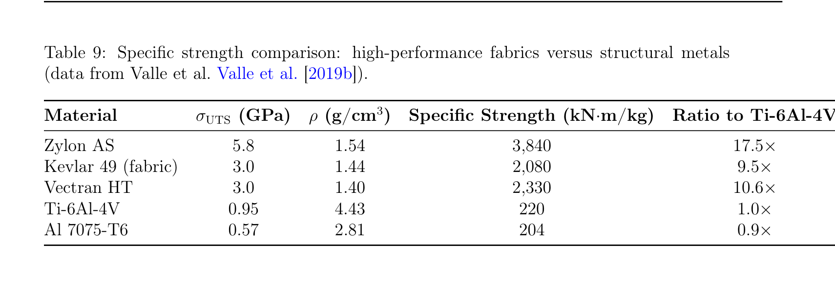
Figure 11: Drag force versus altitude for a 100 m diameter inflatable structure in LEO using CD = 2.4 nominally; Table 21 gives the CD = 3.2 sensitivity cases. The solar-minimum and solar-maximum density curves use exponential interpolation with scale heights H = 53 km and H = 65 km, respectively, anchored to representative NRLMSISE-00 densities at 500 km Picone et al. [2002]. The shaded region illustrates the factor-of-six variation in atmospheric density driven by the solar cycle, which dominates the orbit maintenance propellant budget.
Second-Order Effects
Three additional forces merit consideration for a complete 100 m-class force budget:
Solar radiation pressure (SRP): For a 100 m diameter membrane at 500 km, the SRP force is \( F_{SRP} = (P_\odot/c) \cdot A \cdot (1 + r) \approx (4.56 \times 10^{-6} \text{ N/m}^2) \times 7{,}850 \text{ m}^2 \times 1.5 \approx 0.054 \) N, where \( P_\odot = 1{,}361 \) W/m² is the solar flux, c is the speed of light, and r ≈ 0.5 is the reflectivity. This SRP force is larger than the drag at solar minimum edge-on (0.0035 N) and is within a factor of four of the solar-minimum broadside case (0.174 N), so it is a first-order disturbance for lightly loaded membranes.
Attitude-dependent cross-section: The table presents edge-on (100 m²) and broadside (7,850 m²) as discrete cases, but a real membrane oscillates between attitudes unless actively controlled. The time-averaged effective area depends on AOCS capability—coupling the drag analysis to the AOCS gap (C4). Passive spin stabilisation about the minimum-inertia axis would yield a time-averaged Aeff intermediate between edge-on and broadside, approximately \( 0.5 \times A_{broadside} \approx 3{,}900 \) m², roughly halving the broadside drag but still orders of magnitude above edge-on.
Propellant mass rate derivation: The xenon propellant consumption for Hall thruster drag compensation can be derived as \( \dot{m} = F_D/(g_0 I_{sp}) \), where \( g_0 = 9.81 \) m/s² and \( I_{sp} = 3{,}000 \) s for a representative Hall thruster. For the solar-minimum broadside case (FD = 0.174 N): \( \dot{m} = 0.174/(9.81 \times 3{,}000) = 5.91 \times 10^{-6} \) kg/s = 0.51 kg/day = 187 kg/year. For the solar-maximum broadside sensitivity case (FD = 2.19 N): \( \dot{m} = 2.19/(9.81 \times 3{,}000) = 7.44 \times 10^{-5} \) kg/s = 6.4 kg/day. This is challenging for long-duration missions, but no longer orders of magnitude beyond ISS-class reboost logistics. The corresponding thrust power is \( P = F_D v_e/(2\eta) \), where \( v_e = g_0 I_{sp} = 29{,}430 \) m/s and η = 0.6 (thruster efficiency): yielding 4.3 kW for the solar-minimum broadside case and 54 kW for the solar-maximum broadside sensitivity case. The 1–50 kW range stated in Section 13.2 corresponds to solar-minimum through near-worst-case conditions with some edge-on attitude control.
Air-Breathing Electric Propulsion (ABEP), which collects atmospheric gas for use as propellant, has been proposed for drag compensation in Very Low Earth Orbit (VLEO, 150–450 km) Andreussi et al. [2022]. However, at 500 km the atmospheric density is approximately 100× lower than at the 250–350 km altitudes where ABEP is designed to operate, reducing achievable thrust to 0.001–0.1 mN—orders of magnitude insufficient for the 0.17–2.2 N broadside drag forces computed above. Conventional electric propulsion (Hall effect or gridded ion thrusters) with onboard xenon propellant is the only viable station-keeping option. This propulsion requirement fundamentally constrains mission architecture and represents a significant fraction of the overall mass budget.
11.4 The Missing Theory: AOCS for Pressure-Stabilised Membranes
The gyroelastic body framework of D'Eleuterio and Hughes assumes elastic continua with Cauchy stress tensor constitutive relations—valid for beams, plates, and shells with inherent bending stiffness. Extending this framework to pressure-stabilised inflatable membranes requires four theoretical modifications that represent a significant gap in the published literature:
-
Pressure-stiffness coupling: For an inflatable structure, the effective stiffness \( K_{eff} = K_{membrane} + K_{pressure} \), where the pressure contribution depends on inflation state and couples to deformation through the ideal gas law. When pressure changes due to microleaks or thermal cycling, natural frequencies shift and gyroelastic modes reconfigure—a time-varying system for which fixed-gain controllers may become unstable.
-
Wrinkling constraint: Membranes cannot carry compressive stress; they wrinkle, creating zones where \( \sigma_n = \max(0, T_{membrane} \cdot \varepsilon_n) \). This state-dependent nonlinearity causes mode shapes to change with the deformation state, invalidating the linear modal analysis assumption that underpins both the D'Eleuterio framework and the Cachim optimisation.
-
Orthotropic fabric constitutive model: Space fabrics (Vectran, Kevlar) are woven materials with highly anisotropic stiffness—warp versus weft direction stiffness can differ by 2–5×. The isotropic elastic continuum in the D'Eleuterio formulation requires replacement with an orthotropic constitutive model.
-
Gas-structure interaction coupling: For large inflatable volumes, internal gas has its own dynamics (acoustic modes, pressure wave propagation). This is analogous to liquid sloshing in fuel tanks—a well-studied problem—but the gas-structure coupling for inflatable membranes has received no published treatment.
Each of these extensions builds upon established prior work, and the timeline can be estimated with some granularity:
-
Pressure-stiffness coupling (estimated 3–4 years): The coupling of inflation pressure to membrane stiffness is well-understood for simple geometries through the gossamer structure dynamics literature Jenkins [2001]. The novel challenge is coupling this to the gyroelastic formulation, requiring a pressure-dependent constitutive model within the D'Eleuterio framework. This is the most tractable extension and could be addressed within a focused doctoral programme.
-
Wrinkling constraint (estimated 3–4 years): Tension-field theory Stein and Hedgepeth [1961] provides a well-established framework for membranes that cannot sustain compression. Roddeman et al. Roddeman et al. [1987] developed the modern computational treatment. Integrating wrinkling-induced state-dependent stiffness into gyroelastic eigenvalue analysis is non-trivial but has analogues in rotor dynamics (cracked shaft models with breathing cracks).
-
Orthotropic fabric constitutive model (estimated 1–2 years): Replacing isotropic with orthotropic constitutive relations requires substituting the appropriate fourth-order stiffness tensor into the D'Eleuterio equations. The D'Eleuterio formulation uses the general Cauchy stress tensor, making the extension algebraically systematic. This is the most tractable extension and could constitute the early phase of a doctoral programme or a Master's thesis.
-
Gas-structure interaction coupling (estimated 4–5 years): This is the most novel and uncertain extension. The fuel-sloshing analogy Abramson [1966] is useful but incomplete—gas is compressible while classical sloshing models assume incompressibility. Coupled gas-membrane problems have been studied in the aeroelasticity literature (flutter of inflated membrane wings Leclercq and de Langre [2018]), providing a starting point, but the three-dimensional coupling for large inflatable volumes in the gyroelastic context has no precedent. This is the genuine multi-year research challenge.
The total estimated timeline is 12–15 years if pursued sequentially by individual doctoral candidates, or 5–7 years if pursued in parallel by a coordinated research group with 2–3 concurrent doctoral projects. The sequential estimate of 10–15 years stated in Section 13 is therefore conservative but reasonable. This is among the most significant fundamental research gaps identified in this survey.
12 State of the Art: Robotic In-Orbit Assembly
The vision of large inflatable space structures—100 m-class debris shields, large-aperture antenna reflectors, or orbital habitats exceeding ISS volume—will likely require in-orbit assembly of subsystems that exceed the launch vehicle fairing envelope or are too complex for single-deployment architectures. This section reviews the state of in-space servicing, assembly, and manufacturing (ISAM) robotics, the E-Walker concept for walking robots on large structures, and the critical gap in rigid-to-flexible interface technology that currently prevents assembly on inflatable substrates.
12.1 Assembly Robot Heritage and Current Programmes
In-orbit robotic assembly heritage begins with the ISS, whose construction (1998–2011) relied on the Canadarm2 Space Station Remote Manipulator System (SSRMS): a 17.6 m, 7-DOF arm operating from fixed Power Data Grapple Fixtures (PDGFs) on the truss structure. Canadarm2 demonstrated that large-scale orbital assembly is achievable with telerobotic systems, but at the cost of extensive EVA support and ground-in-the-loop operations.
The ISAM landscape has expanded substantially since ISS assembly. NASA's 2025 State of Play report catalogues 524 capability entries across 145 developers in 21 countries, with over $2 billion in government investment NASA [2025]. Current programmes span multiple technology readiness levels: GITAI's S2 experiment demonstrated autonomous ISS solar array assembly (2021); Project GHOST validated tool manipulation in orbit (2024); DARPA's NOM4D programme targets LEO truss assembly demonstration by Caltech in 2026; and NASA Langley's CIRAS/TALISMAN/SAMURAI/NINJAR ground demonstrations have validated multi-robot truss assembly at 15 m scale Li et al. [2022c], Doggett et al. [2018]. The European PULSAR project targets autonomous assembly of a 12 m telescope mirror Rognant et al. [2019]. Northrop Grumman's MEV-1 (2020) and MEV-2 (2021) represent the first commercial ISAM operations, though these are servicing (docking with client spacecraft) rather than structural assembly.
A critical observation for the present survey is that all 524 entries in the NASA ISAM catalogue address assembly of rigid structures—trusses, beams, modular satellites, and mirror segments NASA [2025]. Not a single entry addresses assembly on or of inflatable/flexible substrates. This is not a mere omission; it reflects a fundamental gap in the technology base: the rigid-to-flexible interface problem remains unsolved (Section 12.3).
12.2 Walking Robots for Large Structure Assembly: E-Walker
The End-over-End Walking Robot (E-Walker) represents the current state of the art in walking manipulators designed for ISAM missions Nair et al. [2022, 2024]. Inheriting the Canadarm2 design philosophy of end-over-end locomotion via grapple fixtures, the E-Walker is a 7-DOF dexterous manipulator at full scale of approximately 475 kg with 350 kg payload capacity—sufficient to handle one primary mirror segment for a 25 m Large Aperture Space Telescope (LAST). Maximum joint torque reaches ∼70 Nm at Joint 2, and finite element analysis confirms maximum link deflection of only 0.04 mm under full payload, with a buckling safety factor exceeding 129 Nair et al. [2022].
A scaled prototype (1.3 m, 12 kg, 2 kg payload at 1:6 scale) has been demonstrated in ground testing. Nair et al. Nair et al. [2024] evaluated 11 concepts of operations for 25 m telescope assembly, concluding that a dual E-Walker configuration is optimal. The 8 m E-Walker requires 4.5 m less workspace than an equivalent fixed-base arm, making walking locomotion particularly advantageous for assembly tasks distributed over large structures.
However, all E-Walker analysis assumes a rigid assembly substrate. The grapple fixtures are ISS-standard PDGFs requiring rigid interfaces with ±10 mm capture tolerance and multi-kN load capacity. When the E-Walker applies 70 Nm joint torques during assembly operations, Newton's third law transmits equal and opposite reactions into the mounting substrate. On the ISS rigid truss, these are absorbed globally; on an inflatable membrane, they would cause local deformation, potential wrinkling, and excitation of global vibration modes. The 475 kg robot's every movement in microgravity creates reaction forces that, on a flexible membrane, propagate as structural disturbances.
12.3 The Rigid-to-Flexible Interface Gap
All existing docking and assembly interfaces assume rigid-to-rigid connections. Liu et al. Liu et al. [2024] designed an androgynous docking port with ±23.5 mm translation tolerance for on-orbit assembly—a practical engineering specification for robotically-assisted mating of rigid modules. ISS Power Data Grapple Fixtures, common berthing mechanisms, and all ISAM interface concepts in the literature share this rigid-to-rigid assumption.
No published work specifically addresses distributed rigid-module attachment to inflatable membranes in the space environment. However, several bodies of adjacent work provide relevant design heritage that should be acknowledged:
-
Tensegrity structures: Tensegrity platforms Skelton and de Oliveira [2009] inherently address the rigid-to-flexible interface through bar-cable connections. NASA Ames' Super Ball Bot Sabelhaus et al. [2015] demonstrates rigid node attachment to tensioned cables in a reconfigurable structure; the load-spreading problem at hardpoint-membrane interfaces is structurally analogous to the bar-cable joint in tensegrity.
-
Deployable antenna feed support: Large deployable mesh antennas (Harris/L3 AstroMesh, Northrop Grumman CRAF) attach a rigid feed assembly to a tensioned cable-net/mesh reflector surface Santiago-Prowald and Rodrigues [2018]. The feed support struts connect rigid hardware to a flexible, tension-stabilised structure—a direct analogue to the rigid-module-on-inflatable-membrane problem.
-
Solar sail boom-membrane attachment: Solar sail designs (e.g., IKAROS, NEA Scout) attach rigid booms to thin-film membranes via reinforced corner fittings. The stress concentration and load distribution at these attachment points have been analysed in the solar sail literature Fernandez et al. [2014].
The gap remains genuine: none of these analogues addresses the full combination of vacuum, thermal cycling, atomic oxygen, micrometeoroid exposure, and zero-gravity dynamics on an inflatable pressure-stabilised substrate. The adjacent work provides starting points for analysis but not validated solutions.
Table 22 summarises the technology readiness of assembly interface approaches.
Table 22: Assembly interface technology readiness for space structures.
| Interface Type | TRL | Heritage | Notes |
|---|---|---|---|
| Rigid-to-rigid (PDGF) | 9 | ISS | Operational since 2001 |
| Rigid-to-rigid (androgynous) | 3–4 | Ground demo | Liu et al. 2024 |
| Rigid-to-flexible (hardpoint) | 2–3 | BEAM ring | Conceptual only |
| Rigid-to-flexible (distributed) | 1–2 | None | No published work |
The closest flight analog is the BEAM-ISS interface: a rigid berthing ring connects the inflatable module to the ISS Node 3 (Tranquility) common berthing mechanism. This is a single rigid-to-inflatable joint at the berthing interface, not a distributed attachment system across the membrane surface. No demonstrated technology exists for attaching multiple rigid subsystems (reaction wheels, solar array drives, communications antennas) to an inflatable membrane at distributed locations. This is a novel finding of this survey and represents a critical research gap.
12.4 Assembly-Enabled Inflatable Platforms: Design Requirements
Based on the analysis in Sections 12.2–12.3, a set of design requirements for assembly-enabled inflatable platforms can be identified:
-
Embedded rigid attachment rings: Metallic rings (0.5–1 m diameter) must be sewn into the inflatable fabric at pre-determined assembly points during manufacturing, with integrated load-spreading plates to distribute reaction forces over sufficient membrane area. The stress concentration factor at such embedded hardpoints (2–5× local stress amplification) must be accounted for in the membrane structural design.
-
Compliance layer: A 3–5 mm silicone or elastomeric foam layer between each rigid attachment ring and the membrane accommodates local deformation and provides vibration isolation, preventing point-load damage to the fabric.
-
Pre-integration requirement: Retrofitting hardpoints onto an already-deployed inflatable is impractical. All assembly interfaces must be designed in and manufactured as part of the inflatable structure before launch. This implies that the assembly concept of operations must be fully defined before the inflatable is manufactured—a significant systems engineering constraint.
-
Active vibration isolation: Small dampers or isolation mounts between each E-Walker grapple point and the membrane surface attenuate reaction forces from assembly operations, reducing excitation of global membrane vibration modes.
-
Pressure-aware operations: Assembly operations that change the mass distribution (adding subsystems) alter both the inertia tensor and the natural frequencies of the inflatable structure. AOCS must accommodate these time-varying dynamics—connecting to the gap identified in Section 11.4.
The E-Walker on an inflatable platform is conditionally feasible with pre-integrated hardpoints, compliance layers, and active vibration isolation. However, none of these solutions has been demonstrated even at component level for space applications. A ground demonstration programme—analogous to NASA Langley's CIRAS/TALISMAN truss assembly demonstrations but on an inflatable test article—would represent a significant advance toward closing this gap.
13 Challenges, Open Questions, and Research Roadmap
The preceding eight technology surveys (Sections 5–12) have documented a paradox that defines the current state of soft inflatable robotic systems for space: individual enabling technologies have reached moderate-to-high readiness levels—Vectran restraint layers at TRL 9 (Section 5), shape memory alloy deployment actuators at TRL 8–9 (Section 7.5), fibre Bragg grating sensors on rigid spacecraft at TRL 7–8 (Section 8.1)—yet no integrated soft inflatable robotic system has been demonstrated in space. This section consolidates the research gaps identified throughout the survey, assesses their severity and interdependence, proposes a structured research roadmap spanning 5-year and 15-year horizons, and identifies the most viable path to a near-term flight demonstration.
13.1 Critical Research Gaps
A systematic analysis of the technology areas reviewed in Sections 5–12 reveals 5 critical gaps, 9 moderate gaps, and 10 minor gaps. Here we consolidate the 5 critical gaps, each of which represents a showstopper for at least one major application domain.
C1: Absence of Quantitative Soft-versus-Rigid Fragmentation Comparison. The central motivation for soft capture in active debris removal (Section 3.2) rests on the proposition that compliant mechanisms reduce fragmentation risk relative to rigid robotic arms. Qualitative evidence supports this argument: Arshad et al. Arshad et al. [2025] identified the "potential to generate fragments during the capturing phase" for rigid systems; Chen et al. Chen et al. [2024] concluded that "single contact-based caging is excessively risky for fast-tumbling targets"; and the RemoveDebris harpoon test demonstrated structural failure of a carbon fibre boom at 20 m s⁻¹ impact Aglietti et al. [2020]. The e.deorbit mission study computed peak joint torques of 195 N m for capture of an 8-tonne ENVISAT tumbling at 5° s⁻¹ Flores-Abad et al. [2014]. However, no published study provides a quantitative fragmentation probability as a function of contact compliance. The catastrophic fragmentation threshold (10 J g⁻¹ specific energy from the IMPACT model Johnson et al. [2001]) has never been applied to a soft-versus-rigid capture force comparison. The fragmentation risk is physically plausible and supported by qualitative assessments—particularly for degraded appendages (solar panels, thermal blankets, antennas) that may have lost 30–60% of their original strength through decades of space environment exposure—but remains experimentally unquantified. This survey adopts the precautionary principle that compliant capture is preferred until quantitative data become available, on the basis that the consequences of inadvertent fragmentation are severe enough to warrant risk-averse technology selection. We propose this as the single highest-priority experimental investigation the community should undertake, requiring hypervelocity and low-velocity impact testing with debris surrogates at varying contact compliance levels.
C2: No Soft Robotic Capture System Has Flown in Space. Despite eight distinct soft or compliant capture approaches documented in Section 3.2—gecko adhesive (TRL 4–5), DEMES grippers (TRL 3–4), bistable soft grippers (TRL 2–3), cryogenic metallic cable robots (TRL 3), inflatable origami arms (TRL 3), flytrap origami (TRL 2–3), thermally qualified multi-layer grippers (TRL 2), and the INSIDeR system concept (TRL ∼4)—none has flown. The gecko adhesive gripper of Jiang et al. Jiang et al. [2017] achieved microgravity validation with 100% capture success rate on spherical targets and capacity exceeding 400 kg, making it the most mature candidate. However, this gripper operates on a rigid robotic arm platform and is more accurately classified as a compliant end-effector on a conventional manipulator (Section 3.1). The gap between ground/parabolic-flight demonstration and orbital flight requires addressing space environment qualification (vacuum outgassing, thermal cycling, radiation exposure over mission-duration timescales) for which limited data exist.
C3: Rigid-to-Flexible Assembly Interface Lacks Specific Published Research. Section 12.3 identified that no published work specifically addresses distributed rigid-module attachment to inflatable membranes in the space environment, though adjacent work in tensegrity structures Skelton and de Oliveira [2009], Sabelhaus et al. [2015], deployable antenna feed supports Santiago-Prowald and Rodrigues [2018], and solar sail boom-membrane attachments Fernandez et al. [2014] provides relevant design heritage. All heritage docking interfaces—ISS PDGF, Common Berthing Mechanism, ClearSpace-1 capture arms, and the androgynous interfaces reviewed by Liu et al. Liu et al. [2024]—assume rigid-to-rigid mating. At the 100-metre scale required for large inflatable debris shields (Section 11.3) or solar power platforms, the inflatable structure becomes a platform onto which functional modules must be assembled in orbit Nair et al. [2024], Li et al. [2022c]. The reaction force problem—how to apply assembly torques to a membrane that deforms under the applied load—has no published solution specific to the space inflatable context. Embedded metallic hardpoint rings represent a plausible design concept informed by the tensegrity and antenna feed analogues, but require detailed finite element analysis of stress concentration at the rigid-flexible interface, none of which has been published.
C4: No Published AOCS Theory for Pressure-Stabilized Inflatable Structures. The control-structure interaction literature reviewed in Section 11.1 addresses rigid trusses, mesh antennas, and mechanically stiffened deployable arrays—structures with inherent stiffness independent of pressurization. Pressure-stabilized inflatable structures exhibit fundamentally different dynamics: stiffness is a function of inflation pressure (a time-varying parameter), membranes wrinkle under compression introducing piecewise-linear stiffness nonlinearity, fabric is anisotropic, and internal gas couples to structural modes D'Eleuterio and Hughes [1984], Jenkins [2001]. The D'Eleuterio–Hughes gyroelastic body framework D'Eleuterio and Hughes [1984, 1986, 1987] provides the most promising theoretical foundation, but requires four extensions: (i) pressure-dependent constitutive model for membrane elements, (ii) wrinkling constraints reflecting piecewise-linear stiffness transitions, (iii) orthotropic fabric constitutive laws, and (iv) gas-structure coupling for internal atmosphere dynamics. Each extension constitutes a substantial theoretical undertaking; collectively they define a research programme of 10–15 years.
C5: Inflatable-Power Integration Gap. The PowerSphere programme (Section 9.2) demonstrated thin-film photovoltaic integration with an inflatable substrate using amorphous silicon cells, achieving 7.25 W kg⁻¹ at 10% cell efficiency Cadogan et al. [2006b]. The programme has been inactive since approximately 2009, and no successor has been identified. Meanwhile, perovskite/CIGS tandem cells have achieved 2100 W kg⁻¹ with 25 µm substrates and greater than 85% power retention after more than 50 years of LEO-equivalent proton irradiation Lang et al. [2020]. The technology exists to revive inflatable-integrated photovoltaics at 20–300× the specific power of the original PowerSphere, yet no programme is pursuing this integration. The gap is institutional rather than technical: flexible PV researchers and inflatable structure researchers operate in separate communities with no overlap programme.
13.2 Integration Challenges at System Level
Beyond individual technology gaps, the fundamental barrier to flight-ready soft inflatable robotic systems is system integration. The preceding sections documented integration deficits across multiple interfaces:
-
Actuation–Structure: Vacuum-gap electrostatic actuators (Section 7.2) achieve >4 N force at 0.7 g mass Sîrbu et al. [2025] using thin-film polymer multilayer construction that is structurally analogous to inflatable membrane wall architectures—yet no study has attempted to laminate actuator layers into an inflatable arm liner. Similarly, the jamming-in-vacuum concept (Section 7.6) has a sound physical basis Fitzgerald et al. [2020] but zero experimental validation in relevant conditions.
-
Sensing–Structure: FBG sensors woven into Vectran webbing have been demonstrated at NASA JSC on 0.61 m and 2.74 m test articles (TRL 4–5) Bally Ribbon Mills and Luna Innovations [2020], while multicore fibre optic shape sensing achieves 0.64 mm position accuracy in soft actuators Galloway et al. [2019]. The same FBG technology could provide both structural health monitoring for inflatable walls and proprioceptive sensing for inflatable robotic arms—a unified sensing architecture that has not been proposed or demonstrated.
-
Power–Thermal–Structure: A large inflatable membrane with thin-film PV on the sun-facing surface, MLI on the space-facing surface, and variable-emissivity coatings for thermal regulation represents a multi-functional surface that would merge the power and thermal subsystems into a single membrane layer. The PowerSphere concept approached this integration using 2004-era materials Cadogan et al. [2006b]; 2025-era perovskite/CIGS cells on Kapton or Mylar substrates would share the same polymer base as inflatable MLI layers Lang et al. [2020], making the integration pathway plausible.
-
AOCS–Deployment: BEAM's deployment anomaly (25 inflation bursts over 7 hours; Section 6.3) illustrates that deployment is a dynamic event with angular momentum consequences. For a free-flying 100-metre inflatable, each inflation pulse imparts momentum to the structure, and as the structure changes shape during deployment its modal frequencies shift—potentially crossing into the AOCS controller bandwidth D'Eleuterio and Hughes [1984]. No published work addresses the coupled deployment–AOCS problem for inflatables.
-
Drag–Power–Thermal Cascade: At 500 km altitude, a 100-metre broadside inflatable experiences drag forces of 0.17–2.2 N depending on solar activity, attitude, and drag coefficient (Section 11.3). To illustrate the cascade quantitatively, consider a worked example for the solar-minimum broadside case (FD = 0.174 N) and the solar-maximum broadside sensitivity case (FD = 2.19 N):
Step 1 — Thrust: Hall thruster at \( I_{sp} = 3{,}000 \) s, exhaust velocity \( v_e = g_0 I_{sp} = 29{,}430 \) m/s.
Step 2 — Power: \( P_{thrust} = F_D v_e/(2\eta) \) where η = 0.6. Solar-min broadside: \( P = 0.174 \times 29{,}430/1.2 = 4.3 \) kW. Solar-max broadside sensitivity case: \( P = 2.19 \times 29{,}430/1.2 = 54 \) kW.
Step 3 — Solar array: At 300 W m⁻² (BOL, triple-junction) and 100 W kg⁻¹ system-level specific power: solar-min requires 14 m² / 43 kg; solar-max requires 180 m² / 540 kg—a major but not prohibitive subsystem allocation.
Step 4 — Waste heat: At 40% combined losses (thruster + PPU): solar-min generates 1.7 kW waste; solar-max generates 21 kW waste.
Step 5 — Radiator: At 200 W m⁻² radiator capacity: solar-min requires 9 m²; solar-max requires 110 m².
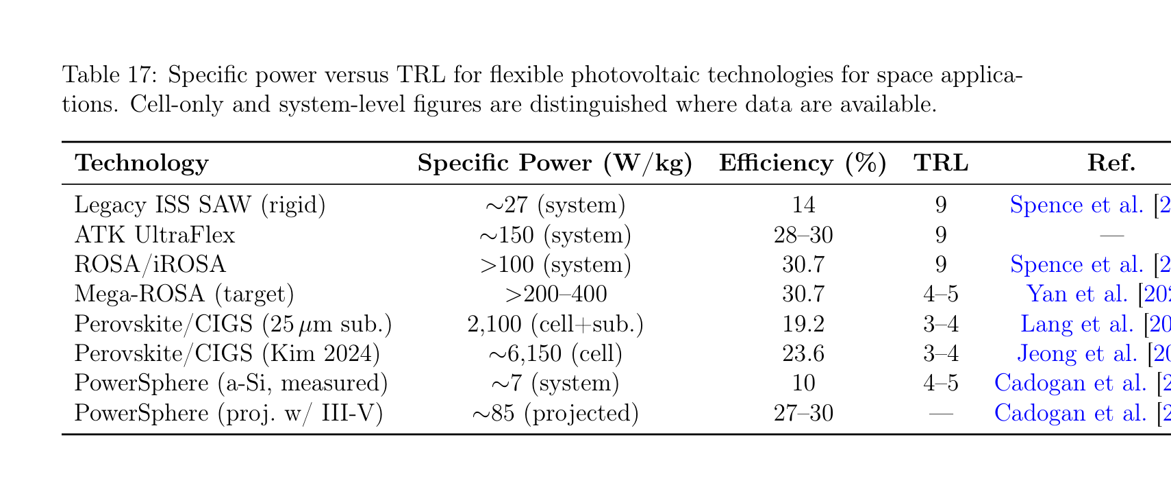
Figure 12: Technology readiness landscape across the eight enabling technology areas reviewed in Sections 5–12. Each marker represents a specific sub-technology; colour indicates TRL band (red: concept TRL 1–3; orange: validated TRL 4–6; green: flight-proven TRL 7–9). While heritage components (Vectran, FBG, ROSA, MLI, Canadarm2) have reached TRL 7–9, the integrative technologies required for soft inflatable robotic systems—vacuum-gap actuators, jamming in vacuum, rigid-to-flexible interfaces, distributed momentum management, and PCM in fabric—remain at TRL 2–3.
This cascade demonstrates that the solar-maximum broadside scenario is challenging without active attitude control to reduce Aeff, confirming that drag budget and AOCS capability are inextricably coupled. Edge-on operation at solar minimum (0.0035 N drag, ∼0.085 kW power, <1 m² array) is feasible; other scenarios require either active attitude management, altitude selection, or both. No published analysis traces this full cascade end-to-end for inflatable platforms, and a complete parametric study spanning altitude, solar cycle, attitude strategy, and propulsion technology is identified as a future research need.
A unifying observation emerges: the integration barriers are not gaps within individual technology disciplines but gaps between disciplines. The soft robotics community, the inflatable structures community, the space power community, and the GNC community each have mature capabilities; the intersections remain unexplored. This fragmentation of the research landscape is itself a structural challenge that programmatic measures (cross-disciplinary funding calls, joint ground demonstrators) must address.
13.3 Proposed Research Roadmap: 5-Year and 15-Year Horizons
Based on the gap analysis above and the technology readiness levels documented in Sections 5–12, we propose a two-horizon research roadmap. The 5-year horizon (2026–2031) targets ground validation and component-level flight demonstration; the 15-year horizon (2026–2041) targets system-level flight demonstration and initial operational capability.
5-Year Horizon (2026–2031). Five priority activities are identified, each addressing one or more critical or moderate gaps:
-
Jamming-in-vacuum experimental validation (addresses M1). Ground experiment: vacuum chamber with sealed granular/layer jamming specimen connected to a pressurized chamber simulating an inflatable interior. Measure stiffness ratio versus pressure differential and compare to terrestrial baselines. Space-compatible granular media candidates include hollow glass microspheres and metallic powder. This experiment is well-defined, moderate-cost, and publishable regardless of outcome. If successful, it validates variable-stiffness robotic elements that are simpler in orbit than on Earth—a paradigm inversion for soft space robotics.
-
FBG-in-Vectran-webbing flight demonstration (addresses M6). Current ground demonstrations at NASA JSC Bally Ribbon Mills and Luna Innovations [2020] have reached TRL 4–5. The next step is a flight experiment on an ISS external payload platform (e.g., MISSE or Bartlett) exposing FBG-instrumented Vectran webbing to the LEO environment (atomic oxygen, UV, thermal cycling, MMOD) for 12–24 months. Success would advance the technology to TRL 6–7 and establish the flight heritage base for inflatable SHM.
-
Perovskite/CIGS fold-deploy-power testing (addresses C5, M5). Deposit perovskite/CIGS tandem cells on 25 µm polymer substrates identical to those used for inflatable MLI. Subject samples to 1000 fold/deploy mechanical cycles, 1000 thermal vacuum cycles (−100°C to 120°C), and atomic oxygen exposure at LEO-equivalent fluences. Measure power output degradation after each environmental stress. This establishes whether the remarkable radiation hardness of perovskite/CIGS Lang et al. [2020] survives the additional mechanical and environmental stresses of inflatable integration.
-
Rigid-to-flexible interface ground prototype (addresses C3). Design, fabricate, and test embedded metallic load-spreader rings sewn into representative multi-layer inflatable fabric during manufacture. Characterize load distribution, stress concentration factors, and modal response under simulated assembly loading. Compare FEA predictions with experimental measurements. This ground programme would produce the first published dataset on rigid-to-flexible assembly interfaces for space inflatables.
-
Gyroelastic theory extension for pressure-stabilized membranes (addresses C4). Mathematical extension of the D'Eleuterio–Hughes framework D'Eleuterio and Hughes [1984, 1986] incorporating pressure-dependent stiffness and fabric orthotropy. Numerical validation against commercial FEM codes for representative inflatable geometries (cylinder, torus, sphere). Publication of the extended theory would establish the foundational AOCS framework that any 100-metre-class inflatable mission will require.
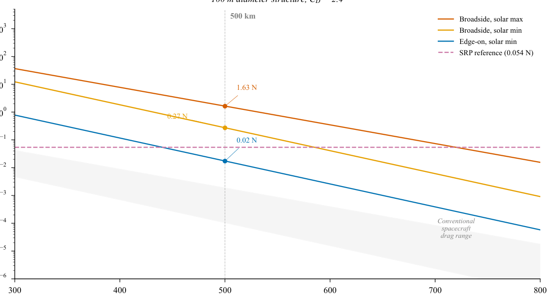
Figure 13: Research roadmap for soft inflatable robotic space systems spanning 5-year and 15-year horizons. Near-term milestones focus on ground validation of critical unknowns (jamming-in-vacuum, FBG flight, perovskite fold-deploy, rigid-flexible interface); long-term milestones target integrated flight demonstrations (soft gripper capture, 10 m inflatable with PV, assembly robot on inflatable substrate, AOCS-qualified inflatable).
15-Year Horizon (2026–2041). Four system-level demonstrations define the long-term roadmap:
-
Soft gripper flight for debris capture (addresses C1, C2). A CubeSat or small-satellite class mission demonstrating compliant capture of a cooperative (then non-cooperative) target in LEO. The gripper subsystem (gecko adhesive, DEMES, or successor technology) operates on an inflatable arm with integrated FBG sensing. This mission provides the first orbital data on soft capture dynamics and validates the fragmentation risk reduction argument with flight telemetry.
-
10-metre inflatable with integrated photovoltaics (addresses C5). A free-flying technology demonstrator deploying a 10-metre-class inflatable membrane with laminated perovskite/CIGS cells, demonstrating fold/deploy survival and power generation in the orbital environment. This bridges the gap between ROSA-class rigid-boom flexible arrays (TRL 9) and the 100-metre inflatable solar platforms envisioned for future missions.
-
Assembly robot on inflatable substrate (addresses C3). A ground or parabolic-flight demonstration of a walking or crawling robot (E-Walker class Nair et al. [2024]) operating on an inflatable test article, attaching and detaching rigid modules via embedded hardpoint interfaces. This validates the rigid-to-flexible assembly concept in representative (reduced) gravity conditions.
-
AOCS-qualified pressure-stabilized inflatable (addresses C4). A free-flying inflatable structure (3–10 metre scale) with onboard AOCS demonstrating three-axis attitude control of a pressure-stabilized membrane in LEO. This validates the extended gyroelastic theory and provides the first flight data on control-structure interaction for inflatable spacecraft.
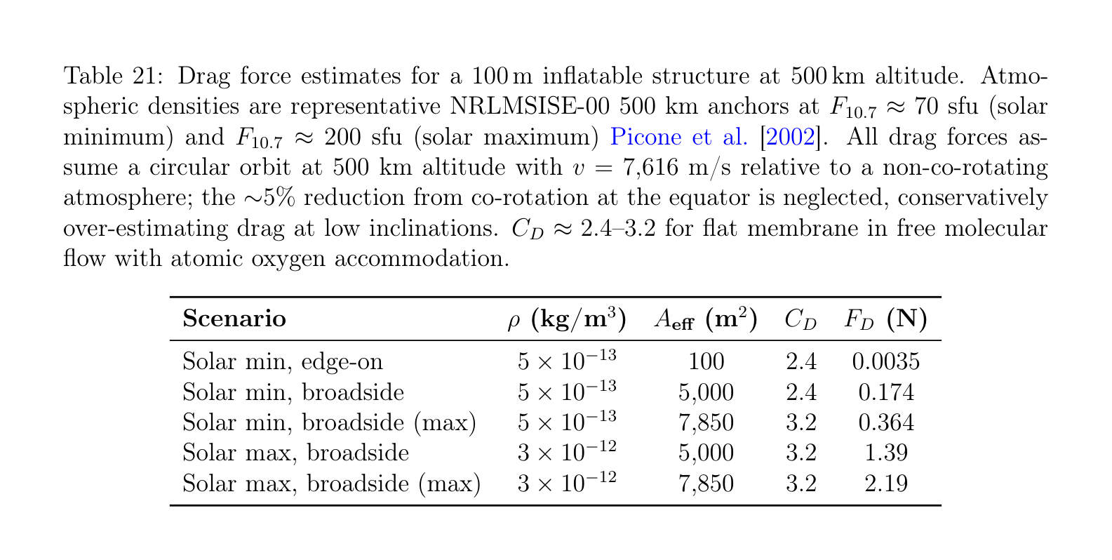
Figure 14: Drag-power-thermal cascade analysis for a 100 m-class inflatable structure in LEO, illustrating how atmospheric drag drives propulsion power requirements, which in turn drive solar array sizing and thermal dissipation budgets. The cascade quantifies the interdependence of the AOCS, power, and thermal subsystems.
13.4 The Path to Flight Demonstration
Among the roadmap milestones, the most flight-ready near-term demonstrator can be identified by selecting the highest-TRL components from each technology area and integrating them into a single mission concept. The analysis in Sections 5–8 suggests the following combination:
-
Capture mechanism: Gecko adhesive gripper (TRL 4–5, microgravity validated, 400 kg capacity) Jiang et al. [2017], noting that this is a compliant end-effector on a conventional arm rather than a fully soft system.
-
Arm structure: Inflatable multi-link arm based on the POPUP concept (TRL 3) Palmieri et al. [2023], using Vectran fabric links with FBG-instrumented webbing.
-
Structural health monitoring: FBG sensors in Vectran webbing (TRL 4–5 ground) Bally Ribbon Mills and Luna Innovations [2020], providing both SHM and proprioceptive shape sensing via multicore FOSS principles Galloway et al. [2019].
-
Deployment: SMA-based hinge deployment for arm segments (TRL 8–9) Costanza and Tata [2020].
This combination achieves an estimated system TRL of 3–4, limited by the inflatable arm structure. A CubeSat-class (12U–16U) demonstrator could validate the complete soft capture concept—deploy inflatable arm, acquire cooperative target, demonstrate FBG-based shape sensing during capture—within a 3–5 year development timeline from programme initiation. The mission would produce the first orbital dataset on: (i) inflatable arm deployment dynamics, (ii) FBG sensor performance in the LEO environment on a flexible structure, and (iii) compliant capture contact dynamics. These three datasets address critical gaps C2, M6, and partially C1, making this demonstrator the highest-value single mission for advancing the field.
The key technical risk is the inflatable arm structure: POPUP-class arms have been demonstrated only in simulation Palmieri et al. [2023], and the transition from analytical design to space-qualified flight hardware requires a focused engineering programme. However, the constituent technologies—Vectran fabric, SMA deployment mechanisms, FBG sensors—each have independent space heritage that de-risks the integration challenge.
A critical observation from the roadmap analysis is that the fragmentation paradox (Section 3.1) will not be resolved by the flight demonstrator alone. The proposed CubeSat mission validates soft capture mechanics but does not generate fragmentation data. Resolving gap C1 requires a parallel ground campaign: hypervelocity and low-velocity impact testing with debris surrogate materials (solar panel fragments, aluminium honeycomb, carbon fibre composite) at representative contact forces, comparing rigid grasp, compliant grasp, and soft envelopment capture modes. Parabolic flight campaigns can provide microgravity validation of the ground results. Together, the flight demonstrator and the ground fragmentation study would establish the quantitative evidence base that the soft ADR proposition currently lacks.
14 Conclusions
This survey has reviewed the state of the art in soft inflatable robotic systems for space applications, covering eight enabling technology areas across 14 sections and synthesizing findings from the active debris removal, space exploration, and robotic assembly domains. Four key findings emerge from this comprehensive analysis.
Finding 1: The Fragmentation Paradox Demands Soft Capture Solutions. The space debris environment has reached a critical state: over 54,000 tracked objects larger than 10 cm, an estimated 140 million fragments between 1 mm and 1 cm, and a total orbital mass exceeding 15,800 tonnes ESA Space Debris Office [2025]. Active debris removal at the rate of at least 5 large objects per year is required to stabilize the LEO population Liou et al. [2010]. Yet the dominant ADR approach—rigid robotic capture, as exemplified by ClearSpace-1—carries an unquantified but non-trivial fragmentation risk for tumbling targets (Section 3.1). Rigid capture of a debris object could generate new fragments, potentially exacerbating the very problem it aims to solve. Soft and compliant capture mechanisms (Section 3.2), by absorbing kinetic energy rather than transmitting contact impulses, offer a system-level safety margin that rigid capture cannot provide. The absence of a quantitative soft-versus-rigid fragmentation comparison (gap C1) is the single most important open research question identified by this survey. Until this comparison is performed, the ADR community is selecting capture mechanisms without the fundamental dataset needed for informed technology selection.
Finding 2: Inflatable Habitats Are Flight-Proven, with a Clear Path to Deep-Space Application. BEAM's 8+ years of continuous operation on the International Space Station has conclusively demonstrated that pressure-stabilized inflatable modules can survive the LEO environment at TRL 9 (Section 4.1). The mass efficiency advantage is decisive: 39 kg m⁻³ for TransHab versus 137–205 kg m⁻³ for metallic ISS modules Valle et al. [2019a]. Vectran-based restraint layers provide specific strengths exceeding 2300 kN m kg⁻¹, an order of magnitude beyond aerospace metals (Section 5.1). Current commercial programmes (Sierra Space LIFE) have demonstrated full-scale burst pressures of 77 psi, exceeding NASA structural requirements by 27% (Section 4.2). The path from BEAM to deep-space habitats requires addressing three challenges: radiation shielding (BEAM's 8–10× higher SPE dose versus metallic modules; Section 4.4), autonomous deployment reliability (BEAM's 25-burst, 7-hour deployment was rescued by ISS crew; Section 6.3), and the 19× volume scale-up from BEAM's 16 m³ to a 300+ m³ deep-space transit habitat. Each challenge is substantive but bounded, with identified mitigation strategies (water-wall radiation shielding, deployment sequencing control, and multi-layer restraint engineering, respectively).
Finding 3: The Space Vacuum Is a Resource, Not Merely an Obstacle. The traditional framing of the space environment as hostile to soft robotics—pneumatic actuation loses its working medium, elastomers outgas, lubricants evaporate—is being overturned by three developments. First, vacuum-gap electrostatic actuators Sîrbu et al. [2025] achieve >4 N force at 0.7 g mass with >100 Hz bandwidth by using internal vacuum gaps as functional elements; these actuators require vacuum and are simpler in orbit than on Earth (Section 7.2). Second, the jamming-in-vacuum principle exploits the ambient orbital vacuum as the external low-pressure reservoir for granular or layer jamming, eliminating the vacuum pump required in terrestrial implementations (Section 7.6); this remains a logical deduction requiring experimental validation (gap M1), but the physics is straightforward. Third, the very existence of pressure-stabilized inflatable structures depends on the vacuum environment providing the pressure differential that creates structural stiffness. Together, these observations suggest that soft inflatable robotic systems for space constitute a distinct engineering discipline—not merely terrestrial soft robotics adapted for space, but a field where the space environment enables capabilities impossible on Earth.
Finding 4: The Critical Barrier Is System Integration, Not Individual Technology Maturity. Perhaps the most significant finding of this survey is negative: no single technology gap is a showstopper for the field. Vectran and Kevlar are flight-proven for inflatable structures (TRL 9). SMA deployment mechanisms are flight-proven (TRL 8–9). FBG sensors have flown on Proba-2 (TRL 7–8). iROSA-class flexible photovoltaics power the ISS (TRL 9). Loop heat pipes transport multi-kilowatt thermal loads (TRL 9). Reaction wheels provide attitude control for the largest operational spacecraft (TRL 9). The barrier is at the interfaces: no programme has integrated FBG sensors into an inflatable structure for flight; no programme is developing photovoltaics on inflatable substrates; no theory addresses AOCS for pressure-stabilized membranes; no interface enables rigid module assembly onto flexible platforms. The field suffers from a fragmentation of its own—not of debris, but of research communities. Soft roboticists, inflatable structure engineers, space power specialists, and GNC researchers each advance their disciplines without the cross-disciplinary programmes needed to integrate their outputs into flight-ready systems.
This survey has attempted to bridge that fragmentation by reviewing all eight enabling technology areas through a single lens: the unifying thesis that the same high-strength fabric technologies (Vectran, Kevlar, Nextel) serve both active debris removal and space exploration applications. The cross-domain connections identified throughout—thermal management informing actuator design (Section 10), MMOD protection materials serving as actuation substrates (Section 5), FBG sensing unifying habitat SHM and robotic proprioception (Section 8.1), and the drag–power–thermal cascade governing 100-metre-class platform architecture (Section 11.3)—are insights that emerge only from the breadth of an integrative review. They cannot be seen from within any single technology discipline.
The research roadmap proposed in Section 13.3 identifies concrete near-term actions: jamming-in-vacuum validation, FBG flight demonstration on inflatable webbing, perovskite/CIGS fold-deploy testing, rigid-flexible interface prototyping, and gyroelastic theory extension. The most flight-ready integrated demonstrator—a gecko-adhesive gripper on an inflatable arm with FBG structural health monitoring—could fly within 3–5 years of programme initiation, generating the first orbital dataset on soft inflatable robotic capture. The longer-term vision—a 10-metre inflatable with integrated photovoltaics, assembly robots operating on inflatable platforms, and AOCS-qualified pressure-stabilized structures—defines a 15-year trajectory toward operational capability.
The space debris crisis demands action on a timescale shorter than the 15-year technology roadmap allows. ClearSpace-1 and its successors will fly rigid capture missions within this decade. The soft robotics and inflatable structures communities must move from component-level demonstration to system-level integration with urgency commensurate with the problem. The technologies exist; the integration does not. Closing the integration gaps identified in this survey is the defining challenge for the next generation of space robotics research.
References
- ESA Space Debris Office. ESA space environment report 2025. Technical report, European Space Agency, 2025. URL https://www.esa.int/Space_Safety/Space_Debris.
- Donald J. Kessler and Burton G. Cour-Palais. Collision frequency of artificial satellites: The creation of a debris belt. Journal of Geophysical Research, 83(A6):2637–2646, 1978. doi:10.1029/JA083iA06p02637.
- Jer-Chyi Liou and Nicholas L. Johnson. Risks in space from orbiting debris. Science, 311(5759):340–341, 2006. doi:10.1126/science.1121337.
- Jer-Chyi Liou and Nicholas L. Johnson. Instability of the present LEO satellite populations. Advances in Space Research, 41(7):1046–1053, 2008. doi:10.1016/j.asr.2007.04.081.
- Jer-Chyi Liou, Nicholas L. Johnson, and N. M. Hill. Controlling the growth of future LEO debris populations with active debris removal. Acta Astronautica, 66(5–6):648–653, 2010. doi:10.1016/j.actaastro.2009.08.005.
- Alexander Ledkov and Vladimir Aslanov. Review of contact and contactless active space debris removal approaches. Progress in Aerospace Sciences, 134:100858, 2022. doi:10.1016/j.paerosci.2022.100858.
- Guglielmo S. Aglietti et al. The active space debris removal mission RemoveDebris: Part 2, in orbit operations. Acta Astronautica, 168:310–322, 2020. doi:10.1016/j.actaastro.2019.09.001.
- Gerald D. Valle et al. System integration comparison between inflatable and metallic spacecraft structures. In 2019 IEEE Aerospace Conference, pages 1–10, 2019a. doi:10.1109/AERO.2019.8742000.
- NASA Johnson Space Center. BEAM ISS year-one science results. Technical Report JSC-CN-39950, NASA, 2017.
- Angel Flores-Abad, Ou Ma, Khanh Pham, and Steve Ulrich. A review of space robotics technologies for on-orbit servicing. Progress in Aerospace Sciences, 68:1–26, 2014. doi:10.1016/j.paerosci.2014.03.002.
- Tomasz Rybus. Robotic manipulators for in-orbit servicing and active debris removal: Review and comparison. Progress in Aerospace Sciences, 151:101055, 2024. doi:10.1016/j.paerosci.2024.101055.
- Yongchang Zhang, Pengchun Li, Jiale Quan, Longqiu Li, Guangyu Zhang, and Dehong Zhou. Progress, challenges, and prospects of soft robotics for space applications. Advanced Intelligent Systems, 5(3):2200071, 2023a. doi:10.1002/aisy.202200071.
- Ion-Dan Sîrbu, Andrea Mazzotta, Umberto Tosi, et al. Vacuum-gap electrostatic multilayer actuators for space robotics. Nature Communications, 16:11414, 2025. doi:10.1038/s41467-025-66232-7.
- Siobhan G. Fitzgerald, Gareth W. Delaney, and David Howard. A review of jamming actuation in soft robotics. Actuators, 9(4):104, 2020. doi:10.3390/act9040104.
- Oluwaseun A. Araromi, Andrew T. Conn, Chen S. Ling, and Jonathan M. Rossiter. Rollable multisegment dielectric elastomer minimum energy structures for a deployable microsatellite gripper. IEEE/ASME Transactions on Mechatronics, 20(1):438–446, 2015. doi:10.1109/TMECH.2014.2329367.
- NASA. NASA Systems Engineering Processes and Requirements. NPR 7123.1B, 2020.
- Muneeb Arshad, Michael C. F. Bazzocchi, and Faraz Hussain. Emerging strategies in close proximity operations for space debris removal: A review. Acta Astronautica, 228:996–1022, 2025. doi:10.1016/j.actaastro.2024.12.017.
- Yan Chen et al. Space debris reliable capturing by a dual-arm orbital robot: Detumbling and caging. arXiv preprint arXiv:2405.00943, 2024. URL https://arxiv.org/abs/2405.00943.
- Hao Jiang et al. A robotic device using gecko-inspired adhesives can grasp and manipulate large objects in microgravity. Science Robotics, 2(7):eaan4545, 2017. doi:10.1126/scirobotics.aan4545.
- Paolo Palmieri, Mario Troise, Luca Salamina, Matteo Gaidano, Matteo Melchiorre, and Stefano Mauro. An inflatable 7-DOF space robotic arm for active debris removal. In Advances in Mechanism and Machine Science (IFToMM WC 2023), volume 148 of Mechanisms and Machine Science. Springer, 2023. doi:10.1007/978-3-031-45770-8_58.
- DuPont. Kevlar 49 Aramid Fiber Technical Data Sheet, 2019.
- Sierra Space Corporation. LIFE habitat ultimate burst pressure test results. Corporate press release, 2024.
- Kriss J. Kennedy. Lessons from TransHAB: An architect's experience. In AIAA Space Architecture Symposium, number AIAA 2002-6105, 2002. doi:10.2514/6.2002-6105.
- Mingxin Wang, Qian Wang, Yakai Xiao, Mingliang Wang, Jianwei Wang, Haowei Wang, and Zhansheng Chen. Review of passive shielding materials for high-energy charged particles in Earth's orbit. Materials, 18(11):2558, 2025. doi:10.3390/ma18112558.
- Timothy L. Weadon. Long term loading properties of Vectran fabric for inflatable space habitats. Master's thesis, West Virginia University, 2013.
- Roberto Destefanis et al. Enhanced space debris shields for manned spacecraft. International Journal of Impact Engineering, 29:217–228, 2003. doi:10.1016/j.ijimpeng.2003.09.019.
- Ji-Hun Cha, Jun-Sang Noh, S. K. Sathish Kumar, et al. Origami multi-layer space shield for cylindrical space structure. Chinese Journal of Aeronautics, 37(10):294–312, 2024. doi:10.1016/j.cja.2024.06.004.
- Douglas A. Litteken. Inflatable technology: Using flexible materials to make large space structures. In Proceedings of SPIE 10966, Earth and Space 2018, volume 10966, 2019. doi:10.1117/12.2500091.
- Koryo Miura. Method of packaging and deployment of large membranes in space. Technical Report 618, Institute of Space and Astronautical Science, 1985.
- Mark Schenk, Andrew D. Viquerat, Keith A. Seffen, and Simon D. Guest. Review of inflatable booms for deployable space structures: Packing and rigidization. Journal of Spacecraft and Rockets, 51(3):762–778, 2014. doi:10.2514/1.A32598.
- Felix Lang et al. Proton radiation hardness of perovskite tandem photovoltaics. Joule, 4(5):1054–1069, 2020. doi:10.1016/j.joule.2020.03.006.
- William Foster-Hall, David J. Harvey, Ling Yin, and Rini Akmeliawati. Soft robotics for space applications: Cryogenic performance of modular metallic cable structures. Soft Robotics, 2025. doi:10.1177/21695172251364758.
- Wei Zhang, Feng Li, Junlin Li, and Qinkun Cheng. Review of on-orbit robotic arm active debris capture removal methods. Aerospace, 10(1):13, 2023b. doi:10.3390/aerospace10010013.
- Andrea Stolfi, Paolo Gasbarri, and Marco Sabatini. A combined impedance–PD approach for controlling a dual-arm space manipulator in the capture of a non-cooperative target. Acta Astronautica, 139:243–253, 2017. doi:10.1016/j.actaastro.2017.07.014.
- Aerospace Corporation. IMPACT satellite breakup model. Technical report, The Aerospace Corporation, 2020.
- ClearSpace SA and European Space Agency. ClearSpace-1: ESA's first space debris removal mission. https://www.esa.int/Space_Safety/ClearSpace-1, 2020. ClearSpace-1 Phase B2/C/D contract.
- Nicholas L. Johnson, Paula H. Krisko, J.-C. Liou, and Phillip D. Anz-Meador. NASA's new breakup model of EVOLVE 4.0. Advances in Space Research, 28(9):1377–1384, 2001. doi:10.1016/S0273-1177(01)00423-9.
- Jun Shintake, Vito Cacucciolo, Dario Floreano, and Herbert Shea. Soft robotic grippers. Advanced Materials, 30(29):1707035, 2018. doi:10.1002/adma.201707035.
- Yuhang Liu, Kai Luo, Shuai Wang, Xiaodong Song, Zhijuan Zhang, Qiang Tian, and Haiyan Hu. A soft and bistable gripper with adjustable energy barrier for fast capture in space. Soft Robotics, 10(1):77–87, 2023. doi:10.1089/soro.2021.0147.
- Yongchang Zhang, Jiale Quan, Pengchun Li, Wenping Song, Guangyu Zhang, Longqiu Li, and Dekai Zhou. A flytrap-inspired bistable origami-based gripper for rapid active debris removal. Advanced Intelligent Systems, 5(7):2200468, 2023c. doi:10.1002/aisy.202200468.
- Fernando Ruiz Vincuería, Begoña C. Arrue, and Aníbal Ollero. Thermally-resilient soft gripper for on-orbit operations. In 2024 IEEE/RSJ International Conference on Intelligent Robots and Systems (IROS), 2024. doi:10.1109/iros58592.2024.10801537. arXiv:2311.08942.
- CT Ingénierie, AirCaptif, and CNES. INSIDeR: Innovative Net and Space Inflatable structure for active Debris Removal. In Proceedings of the 7th European Conference on Space Debris (SDC7), number Paper 714. ESA, 2017.
- CT Ingénierie, AirCaptif, CNES, and ESA. INSIDeR: Ground demonstrator development and net capture simulations. In Proceedings of the 8th European Conference on Space Debris (SDC8), number Paper 91. ESA, 2021.
- Eric L. Christiansen. Handbook for designing MMOD protection. Technical Report NASA/TM-2009-214785, NASA, 2009.
- Roberto Destefanis, Frank Schaefer, Michel Lambert, and Michel Faraud. Selecting enhanced space debris shields for manned spacecraft. International Journal of Impact Engineering, 33(1–12):219–230, 2006. doi:10.1016/j.ijimpeng.2006.09.065.
- NASA. NextSTEP-2 partners develop ground prototypes for deep space habitats. https://www.nasa.gov/nextstep, 2016.
- Lockheed Martin. Bursting the bubble with inflatable habitats. https://www.lockheedmartin.com/en-us/news/features/2022/bursting-the-bubble-with-inflatable-habitats.html, 2022.
- Hassell Studio and European Space Agency. Inflatable lunar habitat at Shackleton crater, 2024.
- Skidmore, Owings & Merrill and European Space Agency. Moon village habitat concept, 2019.
- European Space Agency. Pneumocell: Inflatable lunar habitat for regolith burial, 2018.
- NASA. LOFTID: Low-earth orbit flight test of an inflatable decelerator. https://www.nasa.gov/mission/loftid/, 2022.
- ESA/ESTEC. First European workshop on inflatable space structures, 2002.
- G. D. Valle, D. Litteken, and T. Jones. Review of habitable softgoods inflatable design, analysis, testing, and potential space applications. In AIAA SciTech 2019 Forum, 2019b. doi:10.2514/6.2019-1018. AIAA 2019-1528.
- R. Destefanis et al. Space environment characterisation of Kevlar. In ESA-ESTEC ISME-09, 2009.
- Toyobo Co., Ltd. ZYLON (PBO fiber) technical information. Technical report, Toyobo Co., Ltd., 2005.
- M. A. Said, B. Dingwall, A. Gupta, A. M. Seyam, G. N. Mock, and T. Theyson. Investigation of ultra violet (UV) resistance for high performance fibers. Advances in Space Research, 37(11):2052–2058, 2006. doi:10.1016/j.asr.2005.04.098.
- E. Christiansen et al. Heat-cleaned Nextel in MMOD shielding. In NASA/JSC, 2019. NTRS 20190033497.
- H. G. Pippin et al. Space environment durability of beta cloth in LDEF thermal blankets. In NASA Conference Publication, 1993. NTRS 19940026510.
- B. A. Banks, K. K. de Groh, and S. K. Miller. Low Earth orbital atomic oxygen interactions with materials. Technical report, NASA Glenn Research Center, 2004. NASA/TM-2004-213400.
- M. M. Finckenor and D. Dooling. Multilayer insulation material guidelines. Technical report, NASA Marshall Space Flight Center, 1999. NASA/TP-1999-209263.
- K. J. Kennedy. TransHab inflatable habitat case study. Technical report, NASA, 2016. NTRS 20160011581.
- Gerald D. Valle, Joshua Edgecombe, and Horacio de la Fuente. Damage tolerance testing of a NASA TransHab derivative woven inflatable module. In 50th AIAA/ASME/ASCE/AHS/ASC Structures, Structural Dynamics, and Materials Conference, 2009. doi:10.2514/6.2009-2167. AIAA 2009-2167.
- D. G. Gilmore. Spacecraft Thermal Control Handbook, Volume I: Fundamental Technologies. The Aerospace Press, 2nd edition, 2002. doi:10.2514/4.989117.
- D. Cadogan and S. E. Scarborough. Rigidizable materials for use in gossamer space inflatable structures. In 42nd AIAA/ASME/ASCE/AHS/ASC Structures, Structural Dynamics, and Materials Conference, 2001. doi:10.2514/6.2001-1417. AIAA 2001-1417.
- Craig Underwood, Andrew D. Viquerat, Mark Schenk, Ben Taylor, Chiara Massimiani, Richard Duke, Brian Stewart, Simon Fellowes, Chris Bridges, Guglielmo Aglietti, Ben Sanders, Davide Masutti, and Amandine Denis. InflateSail de-orbit flight demonstration results and follow-on drag-sail applications. Acta Astronautica, 162:344–358, 2019. doi:10.1016/j.actaastro.2019.05.054.
- V. Lappas et al. The InflateSail CubeSat mission: The first European demonstration of drag-sail de-orbiting. In 4S Symposium, 2017.
- R. E. Freeland et al. Recent advances in the rigidization of gossamer structures. In 45th AIAA/ASME/ASCE/AHS/ASC Structures, Structural Dynamics, and Materials Conference, 2004. AIAA 2004-1561.
- R. Allred et al. UV rigidizable carbon-reinforced isogrid inflatable booms. In 43rd AIAA/ASME/ASCE/AHS/ASC Structures, Structural Dynamics, and Materials Conference, 2002. AIAA 2002-1202.
- Adherent Technologies Inc. Rigidization on command (ROC) materials for inflatable spacecraft. In SAE Technical Paper, 2001. 2001-01-2220.
- S. Patel et al. Rigidization analysis of SMA-based inflatable toroidal space structures. Mechanics Based Design of Structures and Machines, 52(11):9334–9364, 2024. doi:10.1080/15397734.2024.2345375.
- Ronen Verker, Eitan Keren, Noa Refaeli, Yoel Carmiel, Asaf Bolker, Dror David, Shai Katz, Erez Sagi, Doron Bashi, Ilan Finkelstein, Tuvia Nahum, Avigdor Haran, Asaf Shemesh Sadeh, Mordechai Ariel, Irina Gouzman, Odelya Amrani, Yonathan Simhony, and Matan Murat. Measurements of material erosion in space by atomic oxygen using the on-orbit material degradation detector. Acta Astronautica, 211:818–826, 2023. doi:10.1016/j.actaastro.2023.07.020.
- Ruiqiong Zhai, Xiaoning Yang, Lixiang Jiang, Hong Gao, Yuxin Zhang, and Zilong Jiao. Synergistic effects of atomic oxygen and thermal cycling in low earth orbit on polymer-matrixed space material. Heliyon, 9(8):e17431, 2023. doi:10.1016/j.heliyon.2023.e17431.
- M. Schenk and S. D. Guest. Inflatable cylinders for deployable space structures. In Proc. Transformables 2013, 2013.
- C. H. M. Jenkins. Gossamer Spacecraft: Membrane and Inflatable Structures Technology for Space Applications, volume 191 of Progress in Astronautics and Aeronautics. AIAA, 2001.
- A. C. Horn. A low cost inflatable CubeSat drag brake utilizing sublimation. Master's thesis, Old Dominion University, 2017.
- D. P. Cadogan, S. E. Scarborough, J. K. Lin, and G. H. Sapna. PowerSphere multifunctional ultraviolet-rigidizable inflatable structures. Journal of Spacecraft and Rockets, 43(5), 2006a. doi:10.2514/1.3360.
- Naifeng Li, Haijun Peng, and Fei Li. Instantaneous optimal control of inflatable folded structures. Acta Astronautica, 195:52–67, 2022a. doi:10.1016/j.actaastro.2022.02.024.
- S. J. Hughes et al. IRVE design overview. In 18th AIAA Aerodynamic Decelerator Systems Technology Conference, 2005. AIAA 2005-1636.
- Thomas W. Murphey, Jeremy A. Banik, and Sergio Pellegrino. TRAC boom technology. AIAA SciTech Forum, (AIAA 2015-0434), 2015.
- Jeremy A. Banik and Thomas W. Murphey. Performance validation of the triangular rollable and collapsible mast. In AIAA Structures, Structural Dynamics, and Materials Conference, number AIAA 2010-2585, 2010.
- C. Sickinger and L. Herbeck. Deployment strategies, analyses, and tests for the CFRP booms of a solar sail. In ESA SP-561, 2004.
- J. Santiago-Prowald and G. Rodrigues. Deployable antennas. In Handbook of Antenna Technologies. Springer, 2018.
- O. A. Araromi, I. Gavrilovich, J. Shintake, S. Rosset, M. Richard, V. Gass, and H. R. Shea. Towards a deployable satellite gripper based on multisegment dielectric elastomer minimum energy structures. In Proc. SPIE 9056, Electroactive Polymer Actuators and Devices (EAPAD) 2014, page 90562G, 2014. doi:10.1117/12.2044667.
- Haopeng Liang, Yong Zhao, and Bingxiao Du. Design, fabrication and modeling of a dielectric elastomer tridimensional minimum energy structure for space mission. Sensors and Actuators A: Physical, 363:114747, 2023. doi:10.1016/j.sna.2023.114747.
- A. Punning, K. J. Kim, V. Palmre, F. Vidal, C. Plesse, N. Festin, A. Maziz, K. Asaka, T. Sugino, G. Alici, et al. Ionic electroactive polymer artificial muscles in space applications. Scientific Reports, 4:6913, 2014. doi:10.1038/srep06913.
- J. S. Mehling, M. A. Diftler, M. Chu, and M. Valvo. A minimally invasive tendril robot for in-space inspection. In First IEEE/RAS-EMBS International Conference on Biomedical Robotics and Biomechatronics (BioRob), pages 690–695, 2006. doi:10.1109/BIOROB.2006.1639170. BioRob 2006.
- X. Ouyang, D. Meng, X. Wang, C. Wang, B. Liang, and N. Ding. Hybrid rigid-continuum dual-arm space robots: Modeling, coupling analysis, and coordinated motion planning. Aerospace Science and Technology, 116:106861, 2021. doi:10.1016/j.ast.2021.106861.
- G. Costanza and M. E. Tata. Shape memory alloys for aerospace, recent developments, and new applications: A short review. Materials, 13(8), 2020. doi:10.3390/ma13081856.
- L. Blanc et al. Solar array root hinge based on shape memory alloy (SMA) actuator. In ESMATS, 2013.
- Y. Zhang, P. Li, J. Quan, L. Li, G. Zhang, and D. Zhou. Progress, challenges, and prospects of soft robotics for space applications. Advanced Intelligent Systems, 5(3):2200071, 2023d. doi:10.1002/aisy.202200071.
- Ahmad Ataka, Taqi Abrar, Fabrizio Putzu, Hareesh Godaba, and Kaspar Althoefer. Model-based pose control of inflatable eversion robot with variable stiffness. IEEE Robotics and Automation Letters, 5(2):3398–3405, 2020. doi:10.1109/LRA.2020.2976326.
- Elliot W. Hawkes, Laura H. Blumenschein, Joseph D. Greer, and Allison M. Okamura. A soft robot that navigates its environment through growth. Science Robotics, 2(8), 2017. doi:10.1126/scirobotics.aan3028.
- Jianglong Guo, Jin-song Leng, and Jonathan M. Rossiter. Electroadhesion technologies for robotics: A comprehensive review. IEEE Transactions on Robotics, 36(2):313–327, 2020. doi:10.1109/TRO.2019.2956869.
- Yoonho Kim, Hyunwoo Yuk, Ruike Zhao, Shawn A. Chester, and Xuanhe Zhao. Printing ferromagnetic domains for untethered fast-transforming soft materials. Nature, 558:274–279, 2018. doi:10.1038/s41586-018-0185-0.
- I. McKenzie, N. Karafolas, H. Henschel, et al. Fiber optic sensing in spacecraft engineering: An historical perspective from the European Space Agency. Frontiers in Physics, 9:719441, 2021. doi:10.3389/fphy.2021.719441.
- Adriana Morana, Emmanuel Marin, Laurent Lablonde, Thomas Blanchet, Thierry Robin, Guy Cheymol, Guillaume Laffont, Aziz Boukenter, Youcef Ouerdane, and Sylvain Girard. Radiation effects on fiber Bragg gratings: Vulnerability and hardening studies. Sensors, 22(21):8175, 2022. doi:10.3390/s22218175.
- T. Baba, N. Saidin, N. F. Hasbullah, et al. Radiation tolerant fiber Bragg gratings: review of FBG sensing. Journal of Optics, 2025. doi:10.1007/s12596-025-02861-x.
- Bally Ribbon Mills and Luna Innovations. Inflatable space habitats use sensors embedded in webbing for structural health monitoring. Technical report, NASA SBIR Program, 2020.
- K. C. Galloway, Y. Chen, E. Templeton, B. Rife, I. S. Godage, and E. J. Barth. Fiber optic shape sensing for soft robotics. Soft Robotics, 6(5):671–684, 2019. doi:10.1089/soro.2018.0131.
- Davide Paloschi, Kirill A. Bronnikov, Sanzhar Korganbayev, Alexey Wolf, Alexander Dostovalov, and Paola Saccomandi. 3D shape sensing with multicore optical fibers: Transformation matrices versus Frenet-Serret equations for real-time application. IEEE Sensors Journal, 21(4):4599–4609, 2021. doi:10.1109/JSEN.2020.3032480.
- Shahriar Sefati, Cong Gao, Iulian Iordachita, Russell H. Taylor, and Mehran Armand. Data-driven shape sensing of a surgical continuum manipulator using an uncalibrated fiber Bragg grating sensor. IEEE Sensors Journal, 21(3):3066–3076, 2021. doi:10.1109/JSEN.2020.3028208.
- Madhav Ramakrishnan, Ginu Rajan, Yuliya Semenova, and Gerald Farrell. Overview of fiber optic sensor technologies for strain/temperature sensing applications in composite materials. Sensors, 16(1):99, 2016. doi:10.3390/s16010099.
- Amanda White, Isaac Little, Anastasiya Artyuk, Nicholas McKibben, Fereshteh Rajabi Kouchi, Claire Chen, David Estrada, and Zhangxian Deng. On-demand fabrication of piezoelectric sensors for in-space structural health monitoring. Smart Materials and Structures, 33(5):055053, 2024. doi:10.1088/1361-665X/ad3d16.
- Pengfei Li, Suyu Xu, Chao Xu, Fei Du, and Shancheng Cao. Development of a miniature dynamic stiffness measurement prototype toward structural health monitoring of space inflatable structures. Measurement, 2022b. doi:10.1016/j.measurement.2022.111051.
- Brian R. Spence, Steven White, Michael LaPointe, Steven Kiefer, Paul LaCorte, Jeremy Banik, Darren Chapman, and Jay Merrill. International space station (ISS) roll-out solar array (ROSA) spaceflight experiment mission and results. In 2018 IEEE 7th World Conference on Photovoltaic Energy Conversion (WCPEC), pages 3522–3529. IEEE, 2018. doi:10.1109/PVSC.2018.8548030.
- Biao Yan, Li Qin, Siyuan Tao, and Guangqiang Fang. Development and challenges of large space flexible solar arrays. Space Solar Power and Wireless Transmission, 2(1):33–42, 2025. doi:10.1016/j.sspwt.2025.03.004.
- Inyoung Jeong, Tae Kyung Lee, Hung Van Tran, Inchan Hwang, Kihwan Kim, et al. Flexible and lightweight perovskite/Cu(In,Ga)Se₂ tandem solar cells. Joule, 9:101794, 2024. doi:10.1016/j.joule.2024.11.011.
- David P. Cadogan, Christina Withrow, John Keller, and Barmac K. Taleghani. Development, design, and testing of PowerSphere multifunctional ultraviolet-rigidizable inflatable structures. Journal of Spacecraft and Rockets, 43(5):1049–1056, 2006b. doi:10.2514/1.3360.
- Edward J. Simburger, James H. Matsumoto, Thomas W. Giants, Alexander Garcia, Simon Liu, Suraj P. Rawal, Alan R. Perry, Craig H. Marshall, John K. Lin, Stephen E. Scarborough, Henry B. Curtis, Mike Piszczor, Thomas W. Kerslake, Todd T. Peterson, and David A. Scheiman. Thin-film technology development for the PowerSphere. Materials Science and Engineering: B, 116(3):265–272, 2005. doi:10.1016/j.mseb.2004.09.035.
- Henry Curtis, Mike Piszczor, Thomas W. Kerslake, Todd T. Peterson, David A. Scheiman, Edward J. Simburger, Thomas W. Giants, James H. Matsumoto, Alexander Garcia, Simon H. Liu, John K. Lin, Stephen E. Scarborough, Daniel J. Gleeson, Suraj P. Rawal, Alan R. Perry, and Craig H. Marshall. Thermal cycle testing of the PowerSphere engineering development unit. In Proceedings of the 19th Space Photovoltaic Research and Technology Conference, 2007. URL https://ntrs.nasa.gov/citations/20090022302. NTRS 20090022302. Contract NAS3-01115.
- Kneev Sharma and Annukka Santasalo-Aarnio. Energy storage systems for space applications. Journal of Energy Storage, 120:117131, 2025. doi:10.1016/j.est.2025.117131.
- Jonathan W. Arenberg, John Flynn, Allan Cohen, Robert Lynch, and John Cooper. Status of the JWST sunshield and spacecraft. In Proc. SPIE 9904, Space Telescopes and Instrumentation 2016: Optical, Infrared, and Millimeter Wave, page 990405. SPIE, 2016. doi:10.1117/12.2234481.
- Hyunsu Kim, Kevin Cheung, Raymond C. Y. Auyeung, David E. Wilson, Kristin M. Charipar, Alberto Piqué, and Nicholas A. Charipar. VO₂-based switchable radiator for spacecraft thermal control. Scientific Reports, 9:11329, 2019. doi:10.1038/s41598-019-47572-z.
- Almamoun Hendaoui, Nath Emond, Mohamed Chaker, and Emile Haddad. VO₂-based smart coatings with improved emittance-switching properties for an energy-efficient near room-temperature thermal control of spacecrafts. Solar Energy Materials and Solar Cells, 117:494–498, 2013. doi:10.1016/j.solmat.2013.07.023.
- Yury F. Maydanik. Loop heat pipes. Applied Thermal Engineering, 25(5–6):635–657, 2005. doi:10.1016/j.applthermaleng.2004.07.010.
- Bogdan Marian Diaconu, Mihai Cruceru, and Lucica Anghelescu. Phase change materials in space systems: Fundamental applications, materials and special requirements—a review. Acta Astronautica, 216:163–213, 2024. doi:10.1016/j.actaastro.2023.12.040.
- Federica Angeletti et al. Attitude dynamics and control of a large flexible space structure by means of a minimum complexity model. Acta Astronautica, 200, 2022. doi:10.1016/j.actaastro.2022.05.047.
- Gabriele M. T. D'Eleuterio and Peter C. Hughes. Dynamics of gyroelastic continua. Journal of Applied Mechanics, 51(2):415–422, 1984. doi:10.1115/1.3167634.
- Gabriele M. T. D'Eleuterio and Peter C. Hughes. Modal parameter analysis of gyroelastic continua. Journal of Applied Mechanics, 53(4):918, 1986. doi:10.1115/1.3171881.
- Gabriele M. T. D'Eleuterio and Peter C. Hughes. Dynamics of gyroelastic spacecraft. Journal of Guidance, Control, and Dynamics, 10(4):401–405, 1987. doi:10.2514/3.20231.
- Christopher J. Damaren and Gabriele M. T. D'Eleuterio. Optimal control of large space structures using distributed gyricity. Journal of Guidance, Control, and Dynamics, 12(5):723–731, 1989. doi:10.2514/3.20467.
- Pedro Rocha Cachim, Will Kraus, Pedro Lourenço, Rodrigo Ventura, and Zachary Manchester. Optimal attitude control of large flexible space structures with distributed momentum actuators. In 2025 IEEE Aerospace Conference, 2025. doi:10.1109/aero63441.2025.11068424. arXiv:2410.07376.
- J. M. Picone, A. E. Hedin, D. P. Drob, and A. C. Aikin. NRLMSISE-00 empirical model of the atmosphere: Statistical comparisons and scientific issues. Journal of Geophysical Research: Space Physics, 107(A12):1468, 2002. doi:10.1029/2002JA009430.
- Yifan Jiang, Jun Zhang, Peng Tian, Tengfei Liang, Zhihui Li, and Dongsheng Wen. Aerodynamic drag analysis and reduction strategy for satellites in very low Earth orbit. Aerospace Science and Technology, 132:108077, 2023. doi:10.1016/j.ast.2022.108077.
- Tommaso Andreussi, Enrico Ferrato, et al. A review of air-breathing electric propulsion: From mission studies to technology verification. Journal of Electric Propulsion, 2:24, 2022. doi:10.1007/s44205-022-00024-9.
- Lee H. Sentman. Free molecule flow theory and its application to the determination of aerodynamic forces. LMSC Technical Report, (LMSC-448514), 1961. doi:10.21236/ad0265409.
- Kenneth Moe and Mildred M. Moe. Gas-surface interactions and satellite drag coefficients. Planetary and Space Science, 53(8):793–801, 2005. doi:10.1016/j.pss.2005.03.005.
- Manuel Stein and John M. Hedgepeth. Analysis of partly wrinkled membranes. Technical Report TN D-813, NASA, 1961.
- D. G. Roddeman, J. Drukker, C. W. J. Oomens, and J. D. Janssen. The wrinkling of thin membranes: Part I–theory. Journal of Applied Mechanics, 54:884–887, 1987. doi:10.1115/1.3173133.
- H. Norman Abramson. The Dynamic Behavior of Liquids in Moving Containers. Number SP-106. NASA, 1966.
- Tristan Leclercq and Emmanuel de Langre. Vortex-induced vibrations of cylinders bent by the flow. Journal of Fluids and Structures, 80:77–93, 2018. doi:10.1016/j.jfluidstructs.2018.03.008.
- NASA. In-space servicing, assembly, and manufacturing (ISAM) state of play—2025 edition. Technical Report NASA/TM-20250008988, NASA Space Technology Mission Directorate, 2025.
- Wenjiang Li, Li Zhong, Weijun Zhu, Zhiyou Xu, Qiang Tang, and Wei Zhan. A survey of space robotic technologies for on-orbit assembly. Space: Science & Technology, 2022:9849170, 2022c. doi:10.34133/2022/9849170.
- William Doggett et al. NASA puts in-space assembly robots to the test (CIRAS/TALISMAN/SAMURAI/NINJAR). Technical report, NASA Langley Research Center, 2018.
- Mathieu Rognant et al. Autonomous assembly of large structures in space (PULSAR project). In 8th European Conference for Aeronautics and Space Sciences (EUCASS), 2019.
- Aadarsh Nair et al. Design engineering a walking robotic manipulator for in-space assembly missions (E-Walker). Frontiers in Robotics and AI, 9, 2022. doi:10.3389/frobt.2022.995813.
- Aadarsh Nair et al. The new era of walking manipulators in space: Feasibility and operational assessment of assembling a 25 m LAST in orbit. Acta Astronautica, 2024. doi:10.1016/j.actaastro.2024.10.002.
- Shuai Liu, Enyang Zhang, Zhenbang Xu, and Jingxu Zhang. Design of docking interfaces for on-orbit assembly of large structures in space. Sensors, 24(20):6534, 2024. doi:10.3390/s24206534.
- Robert E. Skelton and Mauricio C. de Oliveira. Tensegrity Systems. Springer, 2009. doi:10.1007/978-0-387-74242-7.
- Andrew P. Sabelhaus, Jonathan Bruce, Ken Caluwaerts, et al. System design and locomotion of SUPERball, an untethered tensegrity robot. In IEEE International Conference on Robotics and Automation (ICRA), 2015. doi:10.1109/icra.2015.7139590. ICRA 2015.
- Juan M. Fernandez, Vaios J. Lappas, and Andrew J. Daton-Lovett. Completely stripped solar sail concept using bi-stable reeled composite booms. Acta Astronautica, 69:78–85, 2014. doi:10.1016/j.actaastro.2011.02.015.

No comments yet. Be the first to comment!